Consider the given circuit. Assume R= 4 Q. NOTE: This is a multi-part question. Once an answer is submitted, you will be unable to return to this part. 50/33° V R www -j5Q 1622 www 10 Ω 802
Q: P1) For the unit-sized inverter shown in figure Error! Reference source not found., find…
A: Rise time = 24 nsecFall time is 19.2 nsecExplanation:
Q: For the circuit shown in figure below, determine the magnitude and phase of the current I relative…
A:
Q: how can I make this circuit in thinkecad?
A:
Q: A 15.5 kQ resistor and a capacitor are connected in series and then a 12.0 V potential difference is…
A:
Q: This is a practice question from the Signal and Systems course of my Electrical Engineering Program.…
A: Please see the explanation Explanation:Step 1: Step 2: Step 3: Step 4:
Q: Find v, in the circuit shown in Fig. 16.36 given v¸ .= 4u(t)V. 1H m 87 www 202 ww 402
A: Given:we need to find:the expression of Vx.
Q: This is a practice question from the Signal and Systems course of my Electrical Engineering Program.…
A: I have solved in brief and provided the final answer. Explanation:
Q: o H.W: An angle modulated signal has the form: u(t) = 100 cos[2лft + 4 sin 2000лt] where fc 10 MHz.…
A: The angle-modulated signal has the form: u(t) = 100cos[2πfct + 4sin(2000πt)] Where fc = 10 MHz…
Q: An electric field is given as E=x(y+1)+y(z−1)+22 Verify that the field is indeed an electrostatic…
A:
Q: From the following block diagram convert to a Flux diagram, and get its transfer function using…
A: Given block diagram is,Asked to find the transfer function by converting the block diagram to flux…
Q: 3. At what radial frequency will this circuit have an impedance at terminals a and b that is…
A: Given circuit is,Asked to find the radial frequency for entire circuit impedance will be real?
Q: 1. Referring to voltage levels, what is EHV a. Extra High Voltage b. Extreme High Voltage c. Extra…
A: The correct answer is:a. Extra High VoltageExtra-high voltage (EHV) refers to voltages in the range…
Q: HW7.3 (Frequency Mismatch in Amplitude Modulation) A bandlimited continuous- time signal x has the…
A: spectrum of bandlimited signal x(t)with modulation-demodulation scheme,where,
Q: 5. Assuming an operating frequency of 1 kHz, transform the following phasor expressions into a…
A:
Q: Answer all the questions You and your squad have sought shelter in an abandoned industrial site…
A: Hence , we have solved the question.Explanation:Hope you understood well. Have a good day :-)Give me…
Q: Determine Vo and Ip for the circuit in the Figure below +20 V Si Si V www 4.7 Q
A: Refer to the given figure, the diodes are silicon type diodes. Therefore,The forward voltage drop…
Q: List three (3) reasons why a PT100 to 4-20mA transmitter would be used for plant temperature…
A: three (3) reasons why a PT100 to 4-20mA transmitter would be used for plant temperature monitoring…
Q: 09.6
A: The relation with chosen current I2 with mesh current has been explained in detail. If any doubt…
Q: 5.49 For the circuit in Fig. P5.49, determine i₁ (t) and plot it as a function of t for t≥ 0. The…
A: An inductor is a passive electrical component that stores energy in the form of a magnetic field…
Q: VEM (1) = 5 cos (@ct + 20 sin 1000+10 sin 2000) (a) Find the power of the modulated signal. (b) Find…
A:
Q: In order to find I, do I have to find ID2 first? Also, is ID2 as simple as using Ohm's law, I = 10V…
A: Yes Id2 is calculated and then I and the complete method is shown & explained Explanation:Step…
Q: [Ans: VTh = 33.3 V, RT=3.33] 16. Detemine the thevenin's equivalent circuit across 'AB'for the given…
A:
Q: Consider the circuit diagram below, where: v₁(t) = 120 cos(377t) V Π v2(t) = 240 cos (377t + 2) V…
A: see the attachment for details.Explanation:
Q: The equivalent circuit of a 22KVA, 11700/450 V, 60Hz, single-phase loaded transformer when referred…
A: For the given transformer equivalent circuit it is asked to find the percentage voltage regulation
Q: Using branch-current analysis, calculate the current through each branch of the network of Fig. 14.1…
A: I1=5.5554mAI2=−1.515mAExplanation:Step 1: Applying the loop analysis in I1…
Q: 2. Consider a sub-stream i of departures that is generated through Bernoulli splitting of a main…
A: According to the question, consider a sub-stream 'i' of departures that is generated through…
Q: 2. Find h(t) and g(t) for the following circuit: 1 (k) www V₁ (t) + 2(H) m + 0.4 (uF) 1 (k) V2(t)
A: This isa h and g paratmer
Q: (i) For the circuit shown in Figures 2.0a and 2.0b, consider the input D.C. source voltage, E = 10…
A: The given question is solved in step by step process. Explanation: KIRCHHOFFS CURRENT LAW: It…
Q: 2) 2(E), (MA) 30 50 40 This periodic current flows through 10k resistor. Determine the average power…
A: In this question, we need to determine the average power.Average power Pavg = (Irms)2 R WattIrms…
Q: Given the following equivalent circuit of a standard solar cell (b) Standard model: Iph D Ip Rs V VD…
A: The standard model of a solar cell is given…
Q: A conductor of length 0.5 m is moving with the speed of 8 m/s in a perpendicular magnetic flux…
A:
Q: message signal m(t) by its 5th harmonic frequency (i.e., five times the reciprocal of the period…
A: Assumption for the message signalfrom the waveform, to find outa) bandwidth of the FM signalb)…
Q: A 2.2 KVA, 480/4800-V, 50 Hz, single-phase transformer is tested with the following results. Find…
A: A 2.2 KVA, 480/4800 V, 1-ph transformer has short circuit test on LV side and has following test…
Q: A screen, having a Screening Effectiveness (S) of 31.62 at 100 MHz, is located 5 m from a 2 cm…
A: Given Calculating area.
Q: solve this
A: In both cases, the final step is to have the array sorted in ascending order.Explanation:Step…
Q: Required information An ac motor with impedance ZL = (3.2 +3.20) 2 is supplied by an RMS value of…
A: The impedance of AC motor,The supply voltage,
Q: plot is shown Consider a stable system with rational transfer function H(s) whose pole-zero (a)…
A: Since you have posted a question with multiple sub parts, we will provide the solution only to the…
Q: 4.4-1 Given that my(t) is the Hilbert transform of m(t), do the following. (a) Show that the Hilbert…
A:
Q: 3.3
A: Final answer and explanation are in the explanation part.Explanation: Please let me know if there…
Q: 2 dés dt² + 4 de1 dt 1 3c2=11 dc2 dc1 + c₁+2c2=√2 dt dt
A: Given equations:-d/dt(c12)+4d/dt(c1)−3c2=r1d/dt(c2)+d/dt(c1)+c1+2c2=r2 Let x1=c1…
Q: A magnetic core with an air gap is shown below. For a relative permeability is 3500, and the space…
A: Transformer question
Q: I need to find V5 and I5 by using the Nodal Analysis
A: The voltage V5 is V5 =1.3333volts,The current I5 is I5 = 606.06045micro amps. Explanation:
Q: List three (3) disadvantages associated with electric actuators when they are compared to pneumatic…
A: When compared to pneumatic actuators, electric actuators have several disadvantages:Three of them…
Q: 10. Two identical 5 kW, 220 V, 24 A dc shunt machines are to be used as the gene- rator and motor in…
A: (a) The maximum and minimum generator field currents required are 2 A and 2 A respectively. (b) The…
Q: The equivalent circuit of a 22KVA, 11700/450 V, 60Hz, single-phase loaded transformer when referred…
A: Given circuit is,Asked to find the core and copper losses of the transformer.
Q: Formulate matrix systems of equations for NODE and MESH.
A: For the given DC circuit, we need to determine set of nodal and mesh equations in matrix form.
Q: 10. 10 Determine i(t) in the circuit of Fig. 16.35 by means of the Laplace transform. 10 i(t) www…
A: Laplace transform transforms a function of time into a function of a complex variable, allowing for…
Q: A magnetic core with an air gap is shown below. For a relative permeability is 3500, and the space…
A: In this question we need to find the reluctance of air gap.
Q: = 7.9 Three vertical N/2 dipoles are mounted 3λ apart in the same horizontal line and are fed with…
A: According to the question, three vertical λ/2 dipoles are mounted 3λ apart in the same horizontal…
Q: question and solution to part be is shown. Im confused on that K equals too when solving for ni.
A: The value of K in the solution refers to the Boltzmann constant, a fundamental physical constant…
Please answer in typing format
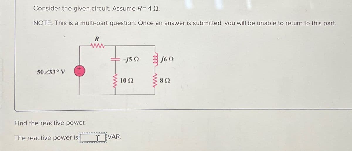
Step by step
Solved in 4 steps with 6 images
- Which of the following is the capacitance of an 88-microfarad and a 108-microfarad starting capacitor connected in series? 196 microfarad 96 microfarad 48 microfarad 40 microfaradWhich of the following is the capacitance of two 20-microfarad running capacitors connected in parallel? 10 microfarad 20 microfarad 30 microfarad 40 microfaradWhat is the impedance of a series L-R-C circuit with L = 10 [mH], R = 0.1 [kΩ], C = 1.0 [µF] and omega (ω) = 10^4 rad/s? Choice A: 0.1 [kΩ] Choice B: 1 [kΩ] Choice C: 10 [kΩ] Choice D: 100 [kΩ]
- A series RLC circuit is connected to a 220V, 60-Hz source,R-40 ohms,L-79.58mH and C-44.21 microFarad. Determine: a.) The Total Impedance b.) The Total Current c.) The Overall Power Factor d.) VR,VL, and VC1. Draw the DC equivalent circuit2. Draw the AC equivalent circuit3. Solve fora. (DC Analysis): Rin(BASE), RTH, VTH, IB, IC, IE, reb. (AC Analysis): Zi, Zo, AvSolve for Vp and Vs. Show your complete solution. (When you try to simulate the circuit in LTSpice where (Vin=0 DC Offset, 10V amplitude, 1MHz frequency), Vp=8V and Vs=40V. I want to learn how to get these values by solving) Will upvote is complete solution and correct. Thank you.
- A coil in a 60-Hz circuit has a resistance of 100 N and an inductance of 0.45 H. Calculate (a) the coil's reactance and (b) the circuit's impedance. *Please make sure the full solution is viewable and does not cut off.An RLC parallel circuit has R= 56Ω, XL= 74Ω, XC= 32Ω. What is the value of Impedance? Answer only clean handwritingA series RLC circuit is connected to a 400-Hz line with an applied voltage of 35.678 V. The resistor has a true power of 14.4W, and there are 12.96 inductive VARs and 28.8 capacitive VARs. Determine the value of ER. (Could you please show the steps so I can understand it? Thanks!)
- I don' t get this, how to know Vin is greater than V ref then it is 5 V? Also, Vin is smaller than V ref then is 0V?In the n-channel JFET circuit given in the figure, I (DDS) = 6mA, V (p) = -4 V. Calculate the values of I(DQ), V(DQ) and V(DSQ) accordingly. I sent you question's image. Thank you.. Please write clearly I should understandThe following is given for a series R-L-C circuit: resistor (R) = 8 Ohms, an inductor (L) = 32 mH and a capacitor (C) = 800uF. The circuit is supplied by a voltage source of e = 120 sin (125t) Volts. What is the real power of the circuit?