Q3: A Moore sequential circuit has three inputs (X2, X1, and Xo) that specify a temperature range in a room. The circuit has two outputs (I and D) that control a heater for the room; 1 =1 causes the heater to increase its heat output, and D = 1 causes the heater to decrease its heat output. If the temperature range is 0, 1, or 2 for three successive clock cycles, the circuit generates I 1, and conversely if the temperature range is 5, 6, or 7 for three successive clock cycles, the circuit generates D = 1; otherwise, I = 0 and D = 0. 1. Draw a state diagram. = 2. Construct a state table. 3. Using D flip-flops, construct a state assigned table. 4. Determine the next-state and output logic expressions. 5. Sketch the corresponding logic circuit.
Q3: A Moore sequential circuit has three inputs (X2, X1, and Xo) that specify a temperature range in a room. The circuit has two outputs (I and D) that control a heater for the room; 1 =1 causes the heater to increase its heat output, and D = 1 causes the heater to decrease its heat output. If the temperature range is 0, 1, or 2 for three successive clock cycles, the circuit generates I 1, and conversely if the temperature range is 5, 6, or 7 for three successive clock cycles, the circuit generates D = 1; otherwise, I = 0 and D = 0. 1. Draw a state diagram. = 2. Construct a state table. 3. Using D flip-flops, construct a state assigned table. 4. Determine the next-state and output logic expressions. 5. Sketch the corresponding logic circuit.

Chapter4: Processor Technology And Architecture
Section: Chapter Questions
Problem 4VE

Related questions
Question
Transcribed Image Text:=
1 causes the heater to decrease its
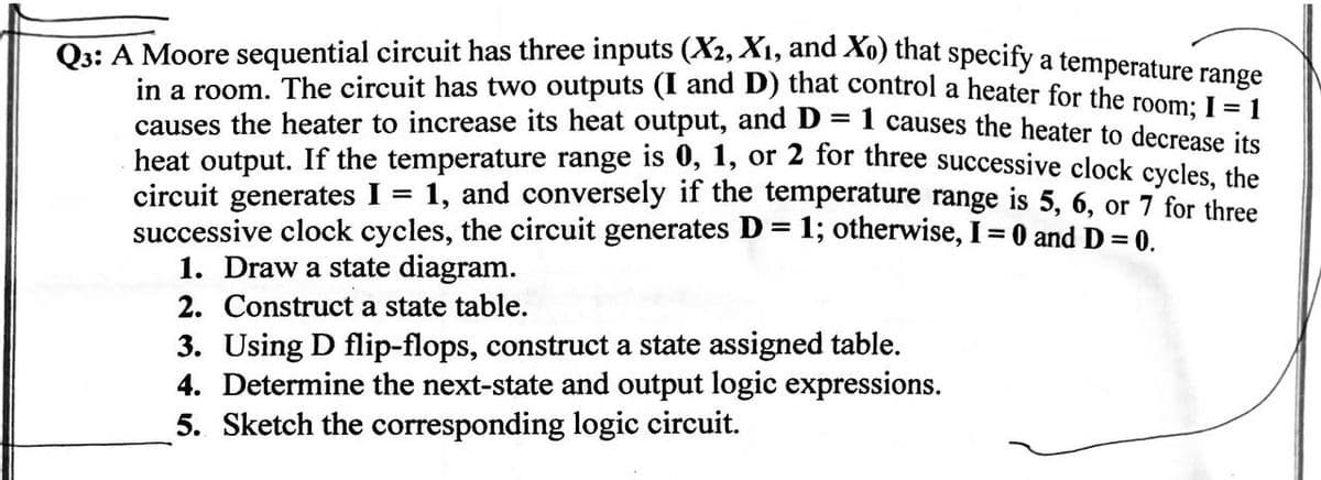
Q3: A Moore sequential circuit has three inputs (X2, X1, and Xo) that specify a temperature range
in a room. The circuit has two outputs (I and D) that control a heater for the room; I = 1
causes the heater to increase its heat output, and D
heat output. If the temperature range is 0, 1, or 2 for three successive clock cycles, the
circuit generates I = 1, and conversely if the temperature range is 5, 6, or 7 for three
successive clock cycles, the circuit generates D = 1; otherwise, I = 0 and D = 0.
1. Draw a state diagram.
2. Construct a state table.
3. Using D flip-flops, construct a state assigned table.
4. Determine the next-state and output logic expressions.
5. Sketch the corresponding logic circuit.
Expert Solution
This question has been solved!
Explore an expertly crafted, step-by-step solution for a thorough understanding of key concepts.

Step by step
Solved in 5 steps

Knowledge Booster


Learn more about
Need a deep-dive on the concept behind this application? Look no further. Learn more about this topic, computer-science and related others by exploring similar questions and additional content below.Recommended textbooks for you
Systems Architecture
Computer Science
ISBN:
9781305080195
Author:
Stephen D. Burd
Publisher:
Cengage Learning
Systems Architecture
Computer Science
ISBN:
9781305080195
Author:
Stephen D. Burd
Publisher:
Cengage Learning