. In a mechanism shown in Fig. 1, the crank OA is 100 mm long and rotates clockwise about t 120 r.p.m. The connceting rod AB is 400 mm long. At a point C on AB, 150 mm from A, the CE 350 mm long is attached. This rod CE slides in a slot in a trunnion at D. The end E is nected by a link EF, 300 mm long to the horizontally moving slider F. Draw the mechanism at le (0° ,45°,90° ) E +200 mm B D 300 mm Figl C
. In a mechanism shown in Fig. 1, the crank OA is 100 mm long and rotates clockwise about t 120 r.p.m. The connceting rod AB is 400 mm long. At a point C on AB, 150 mm from A, the CE 350 mm long is attached. This rod CE slides in a slot in a trunnion at D. The end E is nected by a link EF, 300 mm long to the horizontally moving slider F. Draw the mechanism at le (0° ,45°,90° ) E +200 mm B D 300 mm Figl C

International Edition---engineering Mechanics: Statics, 4th Edition
4th Edition
ISBN:9781305501607
Author:Andrew Pytel And Jaan Kiusalaas
Publisher:Andrew Pytel And Jaan Kiusalaas
Chapter8: Centroids And Distributed Loads
Section: Chapter Questions
Problem 8.91P: What is the ratio L/R for which the uniform wire figure can be balanced in the position shown?

Related questions

Question
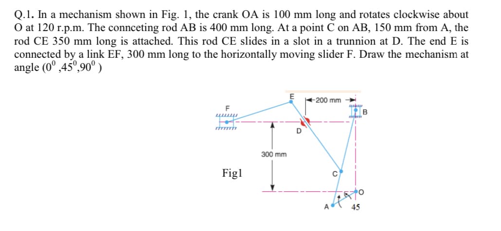
Transcribed Image Text:Q.1. In a mechanism shown in Fig. 1, the crank OA is 100 mm long and rotates clockwise about
O at 120 r.p.m. The connceting rod AB is 400 mm long. At a point C on AB, 150 mm from A, the
rod CE 350 mm long is attached. This rod CE slides in a slot in a trunnion at D. The end E is
connected by a link EF, 300 mm long to the horizontally moving slider F. Draw the mechanism at
angle (0° ,45°,90° )
+200 mm >
F
B
Fot
300 mm
Figl
A
45
Expert Solution
This question has been solved!
Explore an expertly crafted, step-by-step solution for a thorough understanding of key concepts.

This is a popular solution!

Trending now
This is a popular solution!

Step by step
Solved in 4 steps with 4 images

Knowledge Booster


Learn more about
Need a deep-dive on the concept behind this application? Look no further. Learn more about this topic, mechanical-engineering and related others by exploring similar questions and additional content below.Recommended textbooks for you
International Edition---engineering Mechanics: St…
Mechanical Engineering
ISBN:
9781305501607
Author:
Andrew Pytel And Jaan Kiusalaas
Publisher:
CENGAGE L
International Edition---engineering Mechanics: St…
Mechanical Engineering
ISBN:
9781305501607
Author:
Andrew Pytel And Jaan Kiusalaas
Publisher:
CENGAGE L