0 Hz household supply current through a 3-to-1 step-down transformer. It ses a silicon diode that can be modelled as having a constant Vf = 0.84 V rop for any current. vs(t) VL (t) RL (a) What is the peak voltage, US,peak, of the secondary? What is the peak voltage, UL,peak of the rectified output? b) For what fraction of the cycle (in percentage) does the diode conduct? (c) What is the average output voltage, V₁? (state which formula you used: the more accurate formula obtained via integration or the approximate formula) d) What is the average output current, IL? (e) You want to create a DC source with a peak-to-peak ripple voltage, Vr, of 11% of the peak output. (1) What size of capacitor should you add across the output? (2) What is the average voltage now? (State whether you used the more accurate or the approximate formula.)
0 Hz household supply current through a 3-to-1 step-down transformer. It ses a silicon diode that can be modelled as having a constant Vf = 0.84 V rop for any current. vs(t) VL (t) RL (a) What is the peak voltage, US,peak, of the secondary? What is the peak voltage, UL,peak of the rectified output? b) For what fraction of the cycle (in percentage) does the diode conduct? (c) What is the average output voltage, V₁? (state which formula you used: the more accurate formula obtained via integration or the approximate formula) d) What is the average output current, IL? (e) You want to create a DC source with a peak-to-peak ripple voltage, Vr, of 11% of the peak output. (1) What size of capacitor should you add across the output? (2) What is the average voltage now? (State whether you used the more accurate or the approximate formula.)

Power System Analysis and Design (MindTap Course List)
6th Edition
ISBN:9781305632134
Author:J. Duncan Glover, Thomas Overbye, Mulukutla S. Sarma
Publisher:J. Duncan Glover, Thomas Overbye, Mulukutla S. Sarma
Chapter4: Transmission Line Parameters
Section: Chapter Questions
Problem 4.2P: The temperature dependence of resistance is also quantified by the relation R2=R1[ 1+(T2T1) ] where...

Related questions
Question
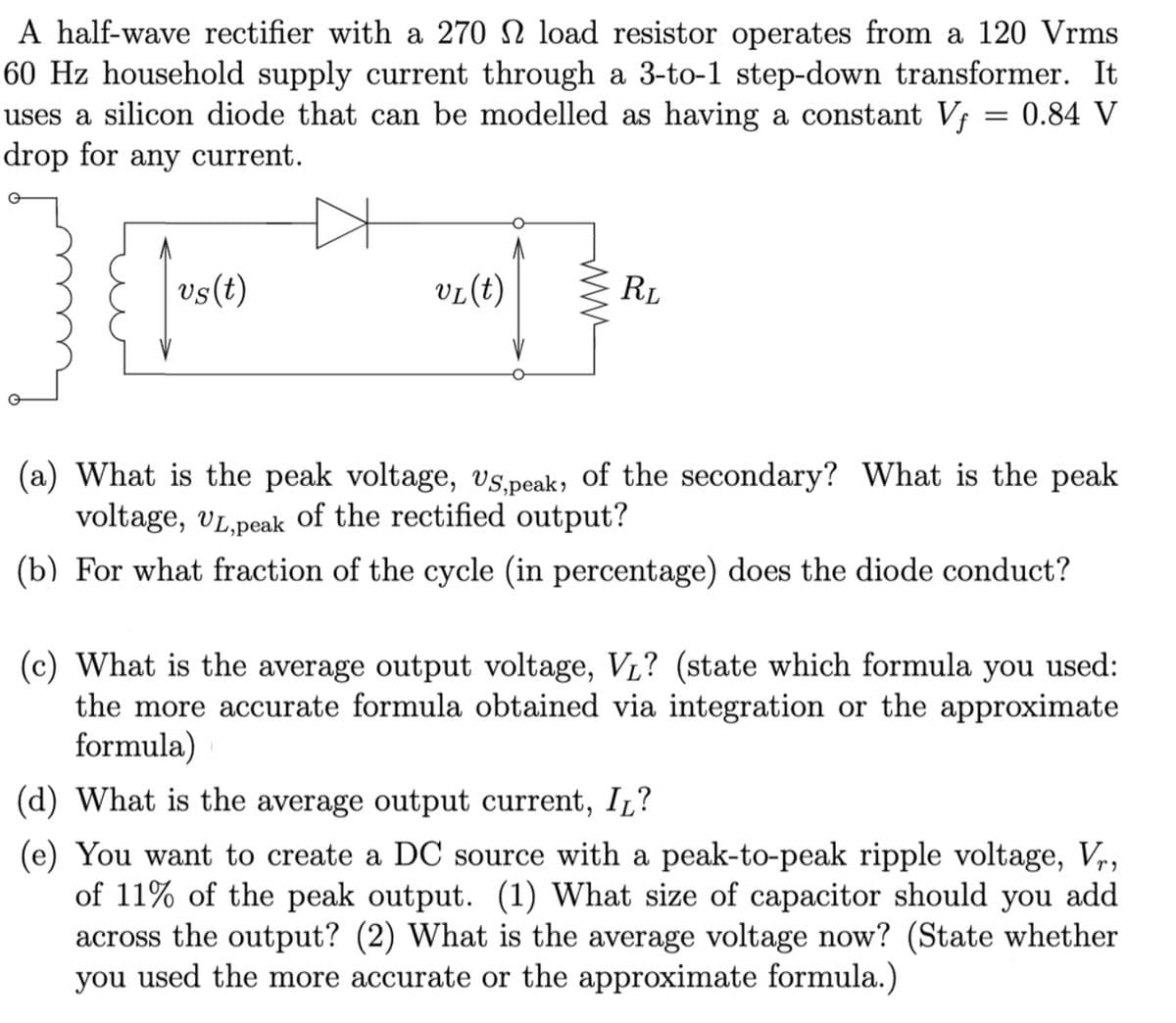
Transcribed Image Text:A half-wave rectifier with a 270 2 load resistor operates from a 120 Vrms
60 Hz household supply current through a 3-to-1 step-down transformer. It
uses a silicon diode that can be modelled as having a constant Vf = 0.84 V
drop for any current.
vs(t)
VL (t)
RL
(a) What is the peak voltage, vs,peak, of the secondary? What is the peak
voltage, UL,peak of the rectified output?
(b) For what fraction of the cycle (in percentage) does the diode conduct?
(c) What is the average output voltage, V₁? (state which formula you used:
the more accurate formula obtained via integration or the approximate
formula) 1
(d) What is the average output current, IL?
(e) You want to create a DC source with a peak-to-peak ripple voltage, Vr,
of 11% of the peak output. (1) What size of capacitor should you add
across the output? (2) What is the average voltage now? (State whether
you used the more accurate or the approximate formula.)
Expert Solution
This question has been solved!
Explore an expertly crafted, step-by-step solution for a thorough understanding of key concepts.

Step by step
Solved in 3 steps with 2 images

Follow-up Questions
Read through expert solutions to related follow-up questions below.
Follow-up Question
You missed the average voltage for part (e)
Solution
Knowledge Booster


Learn more about
Need a deep-dive on the concept behind this application? Look no further. Learn more about this topic, electrical-engineering and related others by exploring similar questions and additional content below.Recommended textbooks for you
Power System Analysis and Design (MindTap Course …
Electrical Engineering
ISBN:
9781305632134
Author:
J. Duncan Glover, Thomas Overbye, Mulukutla S. Sarma
Publisher:
Cengage Learning
Power System Analysis and Design (MindTap Course …
Electrical Engineering
ISBN:
9781305632134
Author:
J. Duncan Glover, Thomas Overbye, Mulukutla S. Sarma
Publisher:
Cengage Learning