0.020 0.082 0.032 4105 Ig-95 (+) (+) E-238.2 EA Load Load EB E2=246.2 A B (-) 0.022 0.082 0.030 Circuit diagram for Prob. 3
0.020 0.082 0.032 4105 Ig-95 (+) (+) E-238.2 EA Load Load EB E2=246.2 A B (-) 0.022 0.082 0.030 Circuit diagram for Prob. 3

Power System Analysis and Design (MindTap Course List)
6th Edition
ISBN:9781305632134
Author:J. Duncan Glover, Thomas Overbye, Mulukutla S. Sarma
Publisher:J. Duncan Glover, Thomas Overbye, Mulukutla S. Sarma
Chapter6: Power Flows
Section: Chapter Questions
Problem 6.53P

Related questions
Question
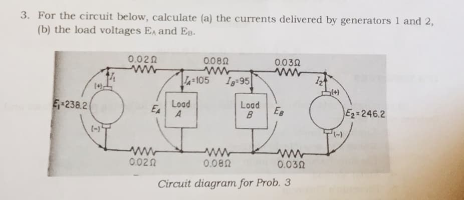
Transcribed Image Text:3. For the circuit below, calculate (a) the currents delivered by generators 1 and 2,
(b) the load voltages EA and EB.
0.020
0.082
0.030
ww
4=105
Ig:95
(+)
(+)
E-238.2
Load
EA
Load
B
EB
E2=246.2
(-)
-),
0.020
0.082
0.032
Circuit diagram for Prob. 3
Expert Solution
This question has been solved!
Explore an expertly crafted, step-by-step solution for a thorough understanding of key concepts.

Step by step
Solved in 2 steps with 2 images

Knowledge Booster


Learn more about
Need a deep-dive on the concept behind this application? Look no further. Learn more about this topic, electrical-engineering and related others by exploring similar questions and additional content below.Recommended textbooks for you
Power System Analysis and Design (MindTap Course …
Electrical Engineering
ISBN:
9781305632134
Author:
J. Duncan Glover, Thomas Overbye, Mulukutla S. Sarma
Publisher:
Cengage Learning
Power System Analysis and Design (MindTap Course …
Electrical Engineering
ISBN:
9781305632134
Author:
J. Duncan Glover, Thomas Overbye, Mulukutla S. Sarma
Publisher:
Cengage Learning