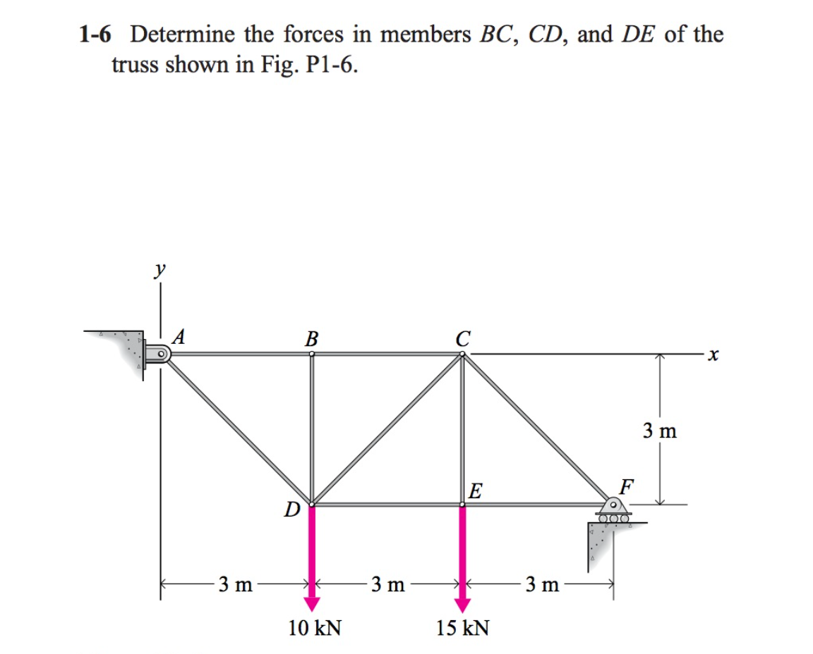
1-6 Determine the forces in members BC, CD, and DE of the truss shown in Fig. P1-6. 3 m E F D O00 3 m 3 m 3 m 10 kN 15 kN
Q: 3. Determine the force in members GF, FC, and CD of the cantilever truss shown in Fig. 5-3. State if…
A: There are many structures that are used in engineering for different purposes and as per the use.…
Q: Sample Problem 5 Determine the forces in members CD, DG, GH of the truss shown by method of…
A:
Q: Fig. P.4.16 shows the plan of a space truss which consists of six pin-jointed members. The member DE…
A:
Q: 3. Determine the forces in members EK, CK and JH of the following truss. Indicate if the members are…
A:
Q: 3. Determine the forces in members DE, CB, and BA of the truss shown in the figure. Using the method…
A: To find force in member AB, BC ,DE
Q: Determine the force in each member of the truss shown in Fig, 6-8a and indicate whether the members…
A:
Q: Determine the force in member CD of the truss shown. 2. Determine the force in member GH of the…
A: This question is related to the Truss Analysis from Structural Analysis. In this question using…
Q: 425. In the Fink truss shown in Fig. P-425, the web members BC and EF are perpendicular to the…
A: Consider the figure,
Q: Classify the truss show in in Fig. as .3 statically determinate, statically * indeterminate, stable…
A: Given:- A truss is given Point A is hinged and Point D is roller supported To determine:- Classify…
Q: 4-84. Determine the for K truss shown in Fig. P4
A: Given:- Force=2000lb To find:- Force in member MG
Q: Classify each of the plane trusses shown as unstable, statically determinate, or statically…
A: As per our guidelines, we only solve first three subparts. Kindly resubmit the question with…
Q: DETERMINE THE FORCE (Ib) IN MEMBER AB OF THE ROOF TRUSS SHOWN GIVEN THE DATA BELOW:
A:
Q: Determine the force in each member of the space truss shown in Fig. 3-38a. The truss is supported by…
A: Consider the support reactions at point A as Ax ,Ay ,and Az; the support reactions at point B as Bx,…
Q: Find the forces in the members of the space truss shown in Fig. P.4.13; suggested axes are also…
A:
Q: 7-24 Determine the forces in members DE, EI, and HI of the truss shown in Fig. 3 kN 8 kN 5 kN 3 m B…
A: The free body diagram of the truss is given below.
Q: Draw the ILD for the forces in members P, Q, R, S of the truss shown in Fig. 3 m 3 m 3 m 3m 水 水 0₁ 3…
A:
Q: Compute the forces in bars AB, AC, DF, and DE of the scissors truss shown in Fig. P-433
A: Moment about J=0ΣMJ=0RA x 60=12x10+12x20+12x30+12x40+12x50RA=30 KRJ=30 K
Q: В D 2 m E YP - 3 m--3 m–|
A: Consider the joint E ∑Fy=0, ⇒FDEsin33.69=6FDE=6/sin33.69 =10.816 kN∑Fx=0,…
Q: HW3: For the truss shown in Fig.3, compute the maximum axial forces that can be developed in members…
A: The axial load or force operating through the centroid or geometric axis of a structure is defined…
Q: For the given truss as shown, determine the force at Members JG, JI, & JH. Use an method in solving…
A:
Q: 5 M B И ЧИ C
A:
Q: 3-3. Determine the bar force in each member of the trusses shown in Fig. 3-35 by the method of…
A:
Q: Q2: Classify the truss shown in Fig.(2) and find the bar forces BD and BG. 20 kN 10 kN +F G. 6m B 2m…
A:
Q: Q2. Determine the force in each member of the compound truss shown in Fig (2), below. 40KN G. SKN 4m…
A:
Q: Determine the force in members GE, GC, and BC of the truss shown in Fig. 6-16a. Indicate whether the…
A: Question is based on the truss subject to hinge and roller support. Loading condition on truss and…
Q: H.W/For the truss as shown in fig. (1) : Determine the force in members (AD, AB , BD). Indicated…
A:
Q: PROBLEM 2: Find the stresses in members BC, BD, and CF for the truss shown. Indicate tension or…
A:
Q: Determine the force in member BD of the truss shown. State whether each member is in tension or…
A: Use force at joints method
Q: 4-60. Determine the stresses in members BC, CG, and BG of the pin-con- nected truss in Fig. P 4-60.…
A: Hi there! you haven't provided the area of the given members for the calculation of stress so, I am…
Q: Classify each of the trusses shown as statically unstable, statically determinate, or statically…
A:
Q: For the trusses shown, determine the forces acting on members PC, PJ and PL. 1 m 1m 2m 16 kN 16 kN…
A:
Q: Classify the truss show in in Fig. as .3 statically determinate, statically * indeterminate, stable…
A: Since, In given truss if a downward force is applied at node E then a mechanism will form and truss…
Q: Calculate the forces in the members FG, GD and CD of the truss shown in Fig. P.15.5 using the…
A: Given: The horizontal and vertical member’s length is 1 m. Consider the figure,
Q: 7-21 Determine the forces in members CD, DG, and GF of the truss shown in Fig. 2000 lb 1000 Ib 3000…
A:
Q: PROBLEM NO. 1. For the trusses shown, determine the forces acting on members PC, PJ and PL. 1m 1 m B…
A:
Q: 4. The Howe truss is subjected to the loading shown. Determine the forces in members GF, CD, and GC.…
A: The given figure is shown below:
Q: . Identify the zero-force members in the truss shown. 2. Redraw the truss without the zero-force…
A: To find zero force members
Q: 4. Determine the force in members DJ, CD, CJ and KJ of the truss which serves to support the deck of…
A: Determine the force in members DJ, CD, CJ and KJ of the truss
Q: For the truss shown in Fig. P-4-4.15. determine independently the forces in bars BD, CD, CE and EF
A:
Q: Determine the force in members EH and GI (Hint: Use section aa) and the force in members HJ and IL…
A:
Q: 3 m H 3m B 10 kN 10 kN 10 kN -4 m-
A:
Q: Determine the forces in members DF, DG, GE, & GF in the given truss shown.
A: Given:- 8 panels at 5m=40m force=30kN To find:- Forces in members DF,DG,GE and GF
Q: 4-83. Determine the force in member KQ Fink truss of Fig. P4-83.
A: Truss is the connection that is made of different elements like joints, members,s or steel…
Q: Problem 2. Determine the force in members DF, DG, and EG of the Howe truss shown in Fig. Knowing…
A:
Q: Q 39/Using the method of joints, indicate all the members of the truss that have zero force. Let P=…
A: According to the guidelines only the first question is being answered. Please repost the question…
Q: Determine (approximately) the forces in the members of the truss shown in Fig. 7-3a. Assume the…
A: Truss is a structure that is widely used to carry a wide variety of loading conditions under…
Q: Calculate the forces in the members of the truss shown in Fig. P.4.3.
A: Truss is a structure made up of three members jointed rigidly and act as a single body. The force in…
Q: 1.18 Determine the smallest safe cross-sectional areas of members CD, GD, and GF for the truss…
A:
Q: 2. Find the forces in members AB, CD, and CH of the truss shown. Indicate whether tension (T) or…
A:
Step by step
Solved in 5 steps with 3 images
- Determine the forces in members FG and AB in terms of P. (Fig. P4.149)A) Calculation of the reaction force FCD at C (directed along the member CD) B) Calculation of the reaction forces at the smooth journal bearing at B (i.e., Bx =?, & Bz =?) C) Calculation of the support reaction forces at the ball-and-socket joint at A (i.e., Ax =?, Ay =?, & Az =?)The vertical force F acts downward at A on the twomemberedframe. Determine the magnitudes of the twocomponents of F directed along the axes of AB and AC.Set F = 350 lb.
- Determine the reactions at supports A and E in Figure P9.48. Area of bar EC = 3 in.2 , IAD = 400 in.4 , and AAD = 8 in.2 ; E = 30,000 kips/in.2438 The center diagonals of the truss in Fig. P-438 can support tension only. Compute the force in each center diagonal and the force in BC DE and FGDetermine the reactions at the supports and draw the bending moment diagram for the following structures. (Ans : θB =16.388/EI, θC =-2.444/EI, Δ=82.819/EI, Ax= - 11.555kN, Ay=17.028kN, MAB=-31.443kNm, Dx=-14.445kN, Dy=30.972kN, MDC=-30.379kNm)
- Determine the resultant R of the Four forces acting on the simple truss. The Fourth force is acting on the node where the 25 KN is at and is directed upward with a magnitude of 15 KN. Specify the points on the x- and y-axes through which R must pass.Determine the internal shear and moment acting at a section passing through point C in the beam shown in Fig. 4–3a.Determine the reactions at the supports and draw the bending moment diagram for the following structures if there are support settlements of 8mm, 5mm and 2mm at A, B and C respectively. Given E=200GPa, I=107mm4 .
- Find the support reactions at A and D, determine the internal forces at the top of member BC. a= 3m b=2m c=6m d=2.5m MA= 380 N.m FB= 200N q0=80N/m q1=160N/mUSE THREE MOMENT EQUATION Determine the reactions and draw the shear and bending moment diagrams for the beams shown. 15.7 Solve Problem 15.4 for the loading shown in Fig. P15.4 and the support settlements of 1 in. at B and ; 1/4 in. at C.Determine the shear and bending moment at point B of the beam shown in Fig. 5.4.