1) Analyze a series RLC circuit like the figure given below and find the equation for Vas in terms of other components (not with their numerical values, just symbolic equation)
1) Analyze a series RLC circuit like the figure given below and find the equation for Vas in terms of other components (not with their numerical values, just symbolic equation)

Introductory Circuit Analysis (13th Edition)
13th Edition
ISBN:9780133923605
Author:Robert L. Boylestad
Publisher:Robert L. Boylestad
Chapter1: Introduction
Section: Chapter Questions
Problem 1P: Visit your local library (at school or home) and describe the extent to which it provides literature...

Related questions
Question
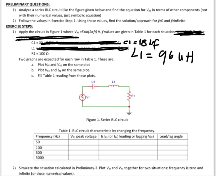
Transcribed Image Text:PRELIMINARY QUESTIONS:
1) Analyze a series RLC circuit like the figure given below and find the equation for Va: in terms of other components (not
with their numerical values, just symbolic equation)
2) Follow the values in Exercise Step-1. Using those values, find the solution/approach for f=0 and f-infinite.
EXERCISE STEPS:
1) Apply the circuit in Figure 1 where VN =5sin(2nft) V. f values are given in Table 1 for each situation
C1 = x
R1 = 100 0
Two graphs are expected for each row in Table 1. These are:
a. Plot Viw and Va: on the same plot
b. Plot Vai and ls on the same plot.
C Fill Table 1 reading from these plots.
Hn gb.=17.
L1
V1
Figure 1. Series RLC circuit
Table 1. RLC circuit characteristic by changing the frequency.
Va1 peak voltage Is es (or In) leading or lagging Vw? Lead/lag angle
Frequency (Hz)
50
100
500
5000
2) Simulate the situation calculated in Preliminary-2. Plot Vw and Vai together for two situations: frequency is zero and
infinite (or close numerical values).
Expert Solution
This question has been solved!
Explore an expertly crafted, step-by-step solution for a thorough understanding of key concepts.

Step by step
Solved in 2 steps

Knowledge Booster


Learn more about
Need a deep-dive on the concept behind this application? Look no further. Learn more about this topic, electrical-engineering and related others by exploring similar questions and additional content below.Recommended textbooks for you
Introductory Circuit Analysis (13th Edition)
Electrical Engineering
ISBN:
9780133923605
Author:
Robert L. Boylestad
Publisher:
PEARSON

Delmar's Standard Textbook Of Electricity
Electrical Engineering
ISBN:
9781337900348
Author:
Stephen L. Herman
Publisher:
Cengage Learning

Programmable Logic Controllers
Electrical Engineering
ISBN:
9780073373843
Author:
Frank D. Petruzella
Publisher:
McGraw-Hill Education
Introductory Circuit Analysis (13th Edition)
Electrical Engineering
ISBN:
9780133923605
Author:
Robert L. Boylestad
Publisher:
PEARSON
Delmar's Standard Textbook Of Electricity
Electrical Engineering
ISBN:
9781337900348
Author:
Stephen L. Herman
Publisher:
Cengage Learning
Programmable Logic Controllers
Electrical Engineering
ISBN:
9780073373843
Author:
Frank D. Petruzella
Publisher:
McGraw-Hill Education

Fundamentals of Electric Circuits
Electrical Engineering
ISBN:
9780078028229
Author:
Charles K Alexander, Matthew Sadiku
Publisher:
McGraw-Hill Education

Electric Circuits. (11th Edition)
Electrical Engineering
ISBN:
9780134746968
Author:
James W. Nilsson, Susan Riedel
Publisher:
PEARSON

Engineering Electromagnetics
Electrical Engineering
ISBN:
9780078028151
Author:
Hayt, William H. (william Hart), Jr, BUCK, John A.
Publisher:
Mcgraw-hill Education,