1 c- Determine the gain and the phase margin of G(s) using the provided bode diagram. Is the closed loop system stable based on your results? 100 Bode Diagram 80 60 40 20 -20 -40 -60 -45 -90 -135 -180 -225 103 102 101 Frequency (rad/s) 100 101 102 Phase (deg) Magnitude (dB)
1 c- Determine the gain and the phase margin of G(s) using the provided bode diagram. Is the closed loop system stable based on your results? 100 Bode Diagram 80 60 40 20 -20 -40 -60 -45 -90 -135 -180 -225 103 102 101 Frequency (rad/s) 100 101 102 Phase (deg) Magnitude (dB)

Introductory Circuit Analysis (13th Edition)
13th Edition
ISBN:9780133923605
Author:Robert L. Boylestad
Publisher:Robert L. Boylestad
Chapter1: Introduction
Section: Chapter Questions
Problem 1P: Visit your local library (at school or home) and describe the extent to which it provides literature...

Related questions
Question
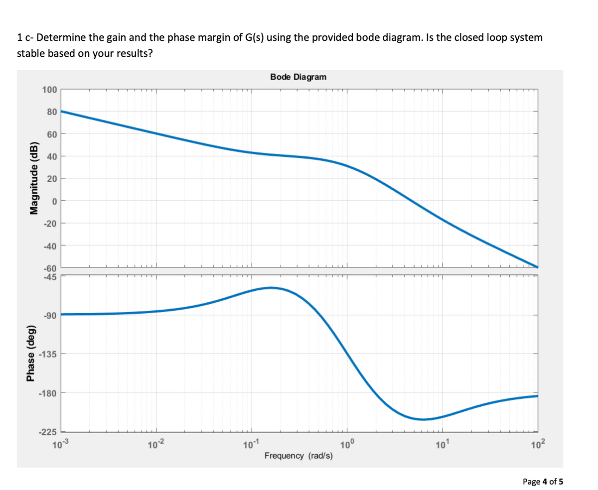
Transcribed Image Text:1 c- Determine the gain and the phase margin of G(s) using the provided bode diagram. Is the closed loop system
stable based on your results?
100
Bode Diagram
80
60
40
-20
-40
-60
-45
-90
-135
-180
-225
10-3
102
101
Frequency (rad/s)
10°
101
102
Page 4 of 5
Phase (deg)
Magnitude (dB)
20
Transcribed Image Text:Given the following system: an electric drill. The input to the drill is electricity. The output is torque.
INZTIR
Setpoint
Torque
G(s)
Torque
KAMZTIAR)
1 a- If the transfer function G(s) is known, what can we use to determine the stability of the closed loop system?
Explain your answer.
1 b-Draw the bode diagram of G(s):
0.1s+1
G(s) =
s+1
Page 2 of 5
Bode Diagram
80
60
40
20
-20
-40
-60
188
135
90
45
-45
-90
-135
-180
102
10°
Frequency (rad/s)
10-1
101
102
Page 3 of 5
Phase (deg)
Magnitude (dB)
Expert Solution
This question has been solved!
Explore an expertly crafted, step-by-step solution for a thorough understanding of key concepts.

Step by step
Solved in 7 steps with 3 images

Knowledge Booster


Learn more about
Need a deep-dive on the concept behind this application? Look no further. Learn more about this topic, electrical-engineering and related others by exploring similar questions and additional content below.Recommended textbooks for you
Introductory Circuit Analysis (13th Edition)
Electrical Engineering
ISBN:
9780133923605
Author:
Robert L. Boylestad
Publisher:
PEARSON

Delmar's Standard Textbook Of Electricity
Electrical Engineering
ISBN:
9781337900348
Author:
Stephen L. Herman
Publisher:
Cengage Learning

Programmable Logic Controllers
Electrical Engineering
ISBN:
9780073373843
Author:
Frank D. Petruzella
Publisher:
McGraw-Hill Education
Introductory Circuit Analysis (13th Edition)
Electrical Engineering
ISBN:
9780133923605
Author:
Robert L. Boylestad
Publisher:
PEARSON
Delmar's Standard Textbook Of Electricity
Electrical Engineering
ISBN:
9781337900348
Author:
Stephen L. Herman
Publisher:
Cengage Learning
Programmable Logic Controllers
Electrical Engineering
ISBN:
9780073373843
Author:
Frank D. Petruzella
Publisher:
McGraw-Hill Education

Fundamentals of Electric Circuits
Electrical Engineering
ISBN:
9780078028229
Author:
Charles K Alexander, Matthew Sadiku
Publisher:
McGraw-Hill Education

Electric Circuits. (11th Edition)
Electrical Engineering
ISBN:
9780134746968
Author:
James W. Nilsson, Susan Riedel
Publisher:
PEARSON

Engineering Electromagnetics
Electrical Engineering
ISBN:
9780078028151
Author:
Hayt, William H. (william Hart), Jr, BUCK, John A.
Publisher:
Mcgraw-hill Education,