1 k2 + 1 1 k2 Si +15 V Si +20 V> GaAs 6 V 1 kQ 2 k2 -15 V Figure -1 Figure -2 Determine V, and Ip for the network in Figure-1 Determine and sketch the output V, for the network given in Figure-2
1 k2 + 1 1 k2 Si +15 V Si +20 V> GaAs 6 V 1 kQ 2 k2 -15 V Figure -1 Figure -2 Determine V, and Ip for the network in Figure-1 Determine and sketch the output V, for the network given in Figure-2

Delmar's Standard Textbook Of Electricity
7th Edition
ISBN:9781337900348
Author:Stephen L. Herman
Publisher:Stephen L. Herman
Chapter18: Resistive-inductive Parallel Circuits
Section: Chapter Questions
Problem 11PP: In an R-L parallel circuit, ET=208 volts, R=2.4k, and XL=1.8k. Find IT.

Related questions
Question
Please explain the question step by step and please care to explain the question in detail with your own sentence and explain why you used that formula, calculations, etc. Thanks in advance.
Transcribed Image Text:1 k2
1
1 k2
+15 V
Si
Si
+20 V
GaAs
6 V
1 k2
2 kN
-15 V
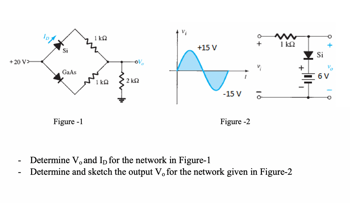
Figure -1
Figure -2
Determine Vo and Ip for the network in Figure-1
Determine and sketch the output V, for the network given in Figure-2
+
Expert Solution
This question has been solved!
Explore an expertly crafted, step-by-step solution for a thorough understanding of key concepts.

Step by step
Solved in 3 steps with 2 images

Knowledge Booster


Learn more about
Need a deep-dive on the concept behind this application? Look no further. Learn more about this topic, electrical-engineering and related others by exploring similar questions and additional content below.Recommended textbooks for you
Delmar's Standard Textbook Of Electricity
Electrical Engineering
ISBN:
9781337900348
Author:
Stephen L. Herman
Publisher:
Cengage Learning
Delmar's Standard Textbook Of Electricity
Electrical Engineering
ISBN:
9781337900348
Author:
Stephen L. Herman
Publisher:
Cengage Learning