1- The equivalent inductance measured between the terminals 1 and 2 for the circuit shown in Fig.1. (a) LI+L2+M (b) LI+L2-M (c) L1+L2+2M (d) L1+L2-2M (e) None of the above 2 m L1 M Fig.1 L2
1- The equivalent inductance measured between the terminals 1 and 2 for the circuit shown in Fig.1. (a) LI+L2+M (b) LI+L2-M (c) L1+L2+2M (d) L1+L2-2M (e) None of the above 2 m L1 M Fig.1 L2

Introductory Circuit Analysis (13th Edition)
13th Edition
ISBN:9780133923605
Author:Robert L. Boylestad
Publisher:Robert L. Boylestad
Chapter1: Introduction
Section: Chapter Questions
Problem 1P: Visit your local library (at school or home) and describe the extent to which it provides literature...

Related questions
Question
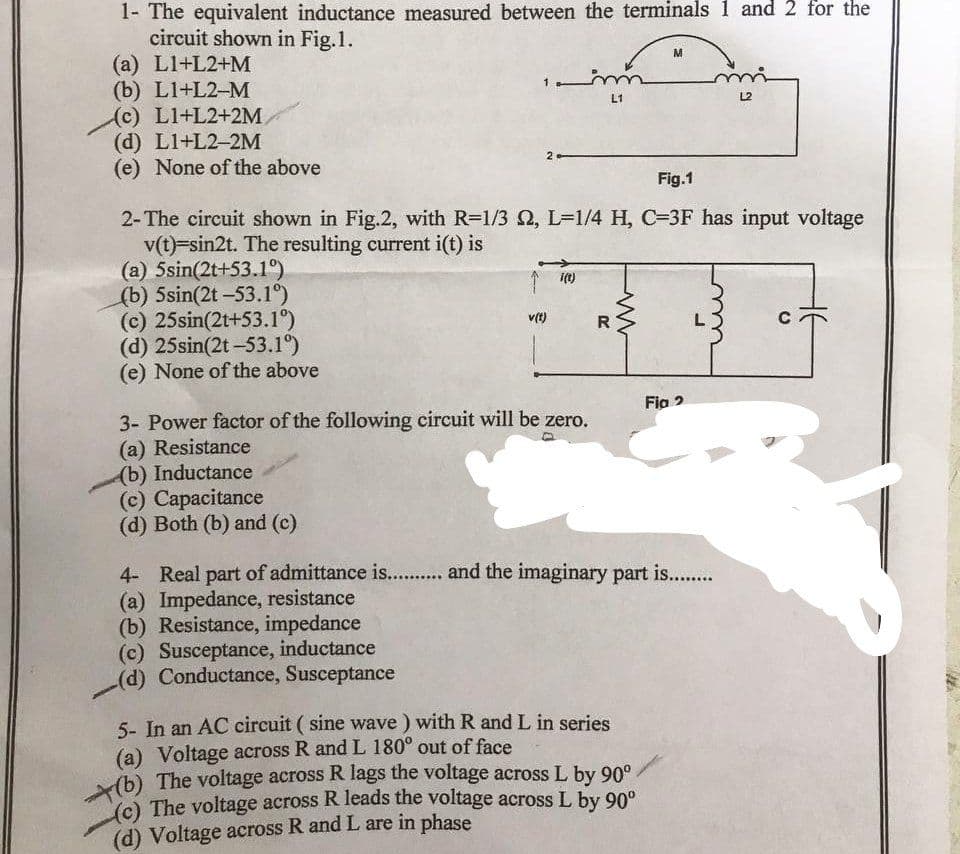
Transcribed Image Text:1- The equivalent inductance measured between the terminals 1 and 2 for the
circuit shown in Fig.1.
(a) LI+L2+M
(b) LI+L2-M
(c) L1+L2+2M
(d) L1+L2-2M
(e) None of the above
(a) 5sin(2t+53.1°)
(b) 5sin(2t -53.1°)
(c) 25sin(2t+53.1°)
(d) 25sin(2t -53.1°)
(e) None of the above
Fig.1
2-The circuit shown in Fig.2, with R=1/3 , L=1/4 H, C=3F has input voltage
v(t)=sin2t. The resulting current i(t) is
v(t)
i(t)
3- Power factor of the following circuit will be zero.
(a) Resistance
(b) Inductance
(c) Capacitance
(d) Both (b) and (c)
(c) Susceptance, inductance
(d) Conductance, Susceptance
m
L1
R
M
5- In an AC circuit (sine wave) with R and L in series
(a) Voltage across R and L 180° out of face
(b) The voltage across R lags the voltage across L by 90°.
(c) The voltage across R leads the voltage across L by 90°
(d) Voltage across R and L are in phase
mi
L2
Fig 2
4- Real part of admittance is........... and the imaginary part is..........
(a) Impedance, resistance
(b) Resistance, impedance
U
Expert Solution
This question has been solved!
Explore an expertly crafted, step-by-step solution for a thorough understanding of key concepts.

Step by step
Solved in 2 steps with 2 images

Knowledge Booster


Learn more about
Need a deep-dive on the concept behind this application? Look no further. Learn more about this topic, electrical-engineering and related others by exploring similar questions and additional content below.Recommended textbooks for you
Introductory Circuit Analysis (13th Edition)
Electrical Engineering
ISBN:
9780133923605
Author:
Robert L. Boylestad
Publisher:
PEARSON

Delmar's Standard Textbook Of Electricity
Electrical Engineering
ISBN:
9781337900348
Author:
Stephen L. Herman
Publisher:
Cengage Learning

Programmable Logic Controllers
Electrical Engineering
ISBN:
9780073373843
Author:
Frank D. Petruzella
Publisher:
McGraw-Hill Education
Introductory Circuit Analysis (13th Edition)
Electrical Engineering
ISBN:
9780133923605
Author:
Robert L. Boylestad
Publisher:
PEARSON
Delmar's Standard Textbook Of Electricity
Electrical Engineering
ISBN:
9781337900348
Author:
Stephen L. Herman
Publisher:
Cengage Learning
Programmable Logic Controllers
Electrical Engineering
ISBN:
9780073373843
Author:
Frank D. Petruzella
Publisher:
McGraw-Hill Education

Fundamentals of Electric Circuits
Electrical Engineering
ISBN:
9780078028229
Author:
Charles K Alexander, Matthew Sadiku
Publisher:
McGraw-Hill Education

Electric Circuits. (11th Edition)
Electrical Engineering
ISBN:
9780134746968
Author:
James W. Nilsson, Susan Riedel
Publisher:
PEARSON

Engineering Electromagnetics
Electrical Engineering
ISBN:
9780078028151
Author:
Hayt, William H. (william Hart), Jr, BUCK, John A.
Publisher:
Mcgraw-hill Education,