1) The following circuits A and B given by figure 2 are used to calculate the resistance of resistors R1 and R2. Circuit A Vs Circuit B Vs R2 Figure 2 a) Explain in detail which circuit is used to measure: i) Very low resistance accurately. ii) Very high resistance accurately.
1) The following circuits A and B given by figure 2 are used to calculate the resistance of resistors R1 and R2. Circuit A Vs Circuit B Vs R2 Figure 2 a) Explain in detail which circuit is used to measure: i) Very low resistance accurately. ii) Very high resistance accurately.

Electricity for Refrigeration, Heating, and Air Conditioning (MindTap Course List)
10th Edition
ISBN:9781337399128
Author:Russell E. Smith
Publisher:Russell E. Smith
Chapter17: Commercial And Industrial Air-conditioning Control Systems
Section: Chapter Questions
Problem 22RQ

Related questions
Question
100%
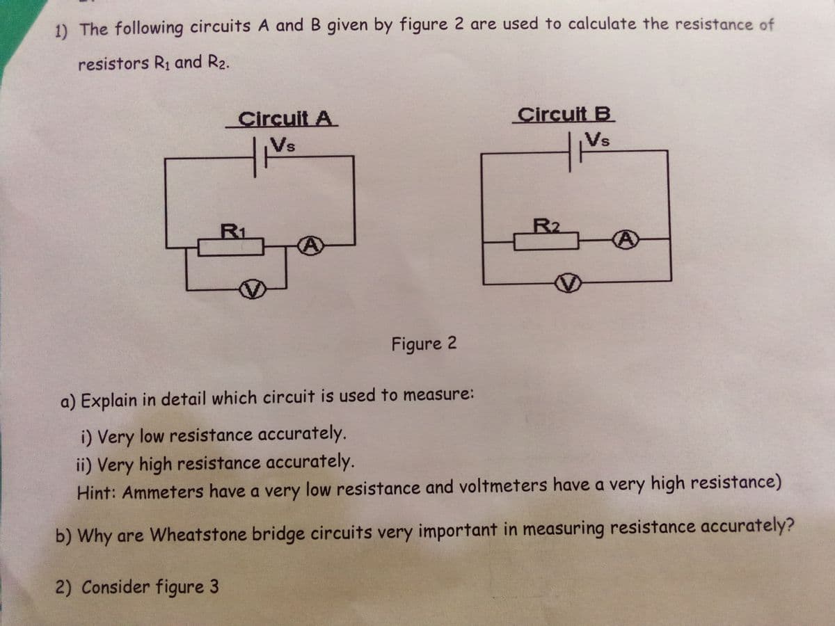
Transcribed Image Text:1) The following circuits A and B given by figure 2 are used to calculate the resistance of
resistors R1 and R2.
Circuit A
Circuit B
Vs
Vs
R1
R2
Figure 2
a) Explain in detail which circuit is used to measure:
i) Very low resistance accurately.
ii) Very high resistance accurately.
Hint: Ammeters have a very low resistance and voltmeters have a very high resistance)
b) Why are Wheatstone bridge circuits very important in measuring resistance accurately?
2) Consider figure 3
Expert Solution
This question has been solved!
Explore an expertly crafted, step-by-step solution for a thorough understanding of key concepts.

Step by step
Solved in 2 steps with 2 images

Knowledge Booster


Learn more about
Need a deep-dive on the concept behind this application? Look no further. Learn more about this topic, electrical-engineering and related others by exploring similar questions and additional content below.Recommended textbooks for you
Electricity for Refrigeration, Heating, and Air C…
Mechanical Engineering
ISBN:
9781337399128
Author:
Russell E. Smith
Publisher:
Cengage Learning
Electricity for Refrigeration, Heating, and Air C…
Mechanical Engineering
ISBN:
9781337399128
Author:
Russell E. Smith
Publisher:
Cengage Learning