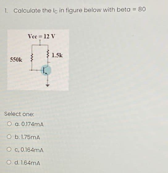
Calculate the lc in figure below with beta = 80 Vcc= 12 V 550k www 1.5k


Q: It is desired to limit the current in an 80-2 resistor to 0.5 A when it is connected to a 50-V power…
A: Brief description: In the above given question we need to calculate the value of unknown resistance…
Q: 1. The magnitude of various voltage drops that occur in an altemator, depends on...... load current…
A: In this question, we have to do fill in blanks, (1) The magnitude of various voltage drops that…
Q: d) Calculate the noise margin for a logic gate with the following logic levels: VIL = 1.0 V, VIH =…
A:
Q: 2. An FM signal is defined as 12 sin(6 x 10⁸ πt + 5 sin 1250 πt). The signal has a total power of 14…
A:
Q: (b) Find V across the load in the AC circuit given in Figure 4.1 (assume that both AC sources have…
A:
Q: Q³: If the transistor is ON state, Vps sat = 0.2 V, K = 300 μA/V², find Vps? VDD=5 V RD =100 Kohm…
A:
Q: Problem You are given the following Digital circuit. out CLK CLK D XO4x O CLK Xi out2 (Ctrl)- Doj…
A:
Q: 4. For the circuit shown in Figure...., determine (a) the total circuit capacitance, (b) the total…
A:
Q: A dc series motor drives a load a 30rev/s and takes a current of 10A when the supply voltage is…
A:
Q: Mass of an electron?
A: The solution is provided in the following section.
Q: What is the flux produced when a 2.5 A current flows through 500 turns coil wound in nonmagnetic…
A: We are authorized to answer one question at a time, since you have not mentioned which question you…
Q: Referring to Figure 9.3, if the generator phase voltage is 400 volts and the load is balanced with…
A: A three-phase AC generator generates three-phase AC electricity by encircling the rotor with extra…
Q: Determine the true power and reactive power of the circuit shown. rms 2V |f=2 kHz с 0.01 μF
A: Given: The voltage source of 2 V The frequency of 2 kHz The capacitance of 0.01 uF
Q: Use the voltage-division principle to find the voltages labeled in Figure 2.14. R-5Q www +91 R₂-100…
A:
Q: LAPLACE AND INVERSE LAPLACE TRANSFORM. 1. L {t² sin 3t}
A:
Q: 2) A system has transfer function: Y(s) 50 R(s) S+50 Find the time constant, T, the settling time,…
A: In this question we will find time constant , settling time , rise time....
Q: What is the voltage induced in the secondary coil of transformer with 400 turns when the varying…
A: We need to find out voltage for transformer and current for given force
Q: Question No.95 What is the number of right half plane poles in closed-loop transfer function: C(s)…
A: Given the closed-loop transfer function, CsRs=505s5+35s4+30s3+210s2+40s+280
Q: 2. Explain electrical contact resistance. Holm model of electrical contact resistance. Contact…
A: It is asked to explain contact resistance and the Holm model of contact resistance. Also it is asked…
Q: m R6 I( ↑ www R5 m RA R₁ m R2 VO R3 R7 m a. Redraw and simplify the circuit. b. Obtain the Norton…
A:
Q: What are the equivalent ac circuit models of an ideal DC voltage and current source?
A: We need to tell about the behaviour of DC source in ac equivalent circuit
Q: A 6-pole, 230-V, 50-Hz, Y-connected, 3-phase induction motor has the following per- phase…
A: Given P=6 VL= 230 V N=950 rpm s= slip f =50 Hz
Q: A Do Da X B What logic gate has the same function as the circuit above?
A: The given logic circuit is,
Q: List the factors Which affects the amount of Electromotive force generated by seebeck effect plz…
A: Given We need to List the factors Which affects the amount of Electromotive force generated by…
Q: 10-10. A 12-bit linear PCM code is digitally compressed into eight bits. The resolution = 0.03 V.…
A: “Since you have posted a question with multiple sub-parts, we will solve first three sub-parts for…
Q: b) When setting the Q-point of a JFET amplifier why is the bias circuit show in Figure 3.1 (b) used…
A: b. To stabilize the Q-point (operating point) bias the circuit. We know that JFET input resistance…
Q: the signal cult thal amp). i. List out the type of signal conditionings involved in the circuit.…
A: Solution- Signal conditioning - It is the manipulation of the signal, it amplifies the signal from…
Q: Determine the true power and reactive power of the circuit shown. Vrms 2V ƒ= 2 kHz с 0.01 μF
A:
Q: A balanced 3-phase, star connected load of 120 kW takes a leading current of 100A with a line…
A: Given, A balanced 3-phase star connected load with, Load power, PL=120 kW Leading current,…
Q: light bulb has a 25 W rating, and it is plugged into a socket with terminals at a 220 V potential…
A: Power is given as the product of voltage and current P =i×v i = v/r Rearrange the equation and…
Q: The shaft torque of a diesel motor driving a 100V dc shunt-wound generator is 25Nm. The armature…
A:
Q: 1.4 A charge of 2 C flowing past a given point each second is a current of 2 A.
A:
Q: interrupts. O O C _setting this bit enables mask able overflow flag.a interrupt-enable flag b sign…
A: Sign flag: It is set if the MSB bit is 1. For signed operations, such a number is treated as…
Q: 8. A 10-pole 25-cycle alternator is directly coupled to, and is dri synchronous motor. How many…
A: Given, An alternator has, Number of poles, Pa = 10 Frequency fa = 25 cycle= 25 Hz A synchronous…
Q: n parallel circuit, the voltage across each branch is the source voltage. equal to Olesser than O…
A:
Q: Explain about time graded and current graded system?
A:
Q: The Synchronizing pulses are transmitted to keep the camera and the picture tube beams in step?…
A: In a monochrome television transmitter, the synchronizing pulses are transmitted to keep the camera…
Q: What will happen if proper polarity is taken for granted in paralleling transformer? If voltages are…
A: The polarity of the transformer means the instantaneous direction of the second induced emf. If the…
Q: Explain about the testing of circuit breakers
A: Given: The objective is to give an explanation about the testing of circuit breaker
Q: Example 7.33. Two coils of inductances 4 and 6 henry are connected in parallel. If their mutual…
A: Given: Two coil of inductances 4 and 6 henry are connected in parallel, L1=4 H L2=6 H Mutual…
Q: VNO- Vcc 15V 2 ka
A: BJT is the three terminal transistor. it is amplify and magnify the signal and it is consist two P-N…
Q: find the solution to the control problem xf² (² max (2.2 - 2u)dt, x=u, x(0) = 1, x(4) = free, and u…
A: It is given that: max∫04 x2-2u dt x˙=ux0=1x4=freeu∈0, 1
Q: H.W. Find the admittance of each set of series elements in Fig. 7. R 100) Y X₁S R≤60 Xc8N (a) Fig. 7…
A: We need to find out admittance of signal circuit
Q: 5. As depicted in Figure 9.3, a 3-phase A connected generator feeds a Y connected load. The…
A: Given data, Line current VL=120V Vph=120V Impedance (Z) =5ohm
Q: Reduce the block diagram shown below to find the transfer function C(s) / R(s). R(s) C(s) G₁(s)…
A:
Q: A 11,000/6,600 V, 3-4, transformer has a star-connected primary and a delta-connected secondary. It…
A:
Q: 15 The voltage 2,000,000 V can be expressed in powers of 10 as: (a) 2 mV (b) 2 kV (c) 2 MV (d) 2 GV
A:
Q: A) What are the addressing mode and physical address for each instruction if you know…
A: Given Register address of a 8086 microprocessor.we need to determine the physical address of the…
Q: a) In a Bipolar Transistor define the quantity B or hFE- How is the device structure of the npn…
A: Transistor:- It is a semiconductor device that have three terminals. Its main function is switching…
Q: Obtain the transfer function H(s) = Vo/V₁. Suppose vi(t) = V₁cos(wt). Obtain the steady state…
A: “Since you have posted a question with multiple sub-parts, we will solve first three sub-parts for…

Step by step
Solved in 2 steps with 1 images


- series regulator a. Calculate Rs, R, & RL, b) find the values of output voltage (Vout), Current flowing through Resistor R, Voltage across Rs, Voltage across resistor R, current flowing through the collector (Iz), and Current flowing through zener diode.1) 169sin 377t a) What is the peak factor? b) What is the form factor?activated as figure Draw the ID, VGS characteristic and show the operating point Q on the load line. NOTE = k = 0.5mA / V² and VGSth = 1v
- Determine the Ib (base current) in the given circuit if VBB = 15V, Vcc = 15V, RB = 15k ohms, RC = 1k ohms. Assume β = 100.For the circuit in the figure, let V input = 8V, Ri = 12ohms, RL = 10ohms, and VZ = 3.3V. Determine the voltages and currents of the resistors and the current of the zener diode.The Zener-diode regulator circuit shown below is to be used to provide a stabilised output to the load. The zener diode characteristic is also shown. Find the load voltage and source current if the battery voltage is 24 V, series resistance is 1.2 kohm and load resistance is 6 kohm.
- Q. The IC used in OPAMP is LM 741. True FalseHalf-wave battery charger Consider the battery charging circuit in Figure. with Vm= 20V, R= 10Ωand VB= 14V. Find the peak current assuming an ideal diode.Given zener voltage at 9V, input voltage at 12Vdc to 15Vdc and ILmax at 40mA. What is Rsmin if Izmax rated is 50mA?
- Design a CT-FWR to supply a load of (50) with a waveform of the following specifications: - Vdc = 12 V Ripple factor = 0.1 % the main power supply is (220 Vrms, 50 Hz). Determine the following values: - 1- The value of capacitor filter. 2- The maximum load voltage (VmR) 3- The transformer turns ratio (a). 4- The RMS value of the load voltage. 5- Draw the output waveform. (assume ideal diodes)Determine the DC currents (IB, IC and IE) and dc junction voltages (VBE, VCE and VCB) Use the following values: VBB = 4V RB = 5 kΩ RC = 188 Ω VCC = 23 V βDC = 73The average value of the output voltage with PWM is Vo = 5 V. If the on state duration Ton is 5 µs and supply voltage Vin = 20 V, find the duty ratio d, switching period Ts and switching frequency fs of the system. Draw the waveforms for Vin and Vo voltages stating on and off durations.