1. Determine the external reactions at the roller and pin supporting the above beam. 2. Determine the internal reactions (shear and bending moment) at points B, D and F using the method of sections. 3. Determine the shear and moment equations for the beam section under the triangular load, and the shear and moment equations for the beam section under the rectangular load.
1. Determine the external reactions at the roller and pin supporting the above beam. 2. Determine the internal reactions (shear and bending moment) at points B, D and F using the method of sections. 3. Determine the shear and moment equations for the beam section under the triangular load, and the shear and moment equations for the beam section under the rectangular load.

Chapter2: Loads On Structures
Section: Chapter Questions
Problem 1P

Related questions

Question
Note: n=34
X: multiplied by ..(not a value it's a sign)
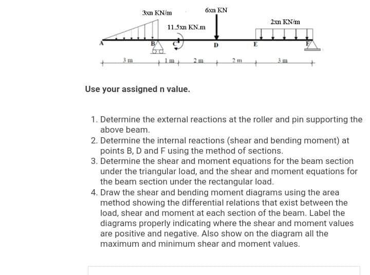
Transcribed Image Text:óxn KN
3xn KN/m
2xn KN/m
11.5xn KN.m
B
D
3 m
2 m.
2 m
3 m
Use your assigned n value.
1. Determine the external reactions at the roller and pin supporting the
above beam.
2. Determine the internal reactions (shear and bending moment) at
points B, D and F using the method of sections.
3. Determine the shear and moment equations for the beam section
under the triangular load, and the shear and moment equations for
the beam section under the rectangular load.
4. Draw the shear and bending moment diagrams using the area
method showing the differential relations that exist between the
load, shear and moment at each section of the beam. Label the
diagrams properly indicating where the shear and moment values
are positive and negative. Also show on the diagram all the
maximum and minimum shear and moment values.
Expert Solution
This question has been solved!
Explore an expertly crafted, step-by-step solution for a thorough understanding of key concepts.

Step by step
Solved in 3 steps with 3 images

Knowledge Booster


Learn more about
Need a deep-dive on the concept behind this application? Look no further. Learn more about this topic, civil-engineering and related others by exploring similar questions and additional content below.Recommended textbooks for you

Structural Analysis (10th Edition)
Civil Engineering
ISBN:
9780134610672
Author:
Russell C. Hibbeler
Publisher:
PEARSON

Principles of Foundation Engineering (MindTap Cou…
Civil Engineering
ISBN:
9781337705028
Author:
Braja M. Das, Nagaratnam Sivakugan
Publisher:
Cengage Learning
Structural Analysis (10th Edition)
Civil Engineering
ISBN:
9780134610672
Author:
Russell C. Hibbeler
Publisher:
PEARSON
Principles of Foundation Engineering (MindTap Cou…
Civil Engineering
ISBN:
9781337705028
Author:
Braja M. Das, Nagaratnam Sivakugan
Publisher:
Cengage Learning

Fundamentals of Structural Analysis
Civil Engineering
ISBN:
9780073398006
Author:
Kenneth M. Leet Emeritus, Chia-Ming Uang, Joel Lanning
Publisher:
McGraw-Hill Education


Traffic and Highway Engineering
Civil Engineering
ISBN:
9781305156241
Author:
Garber, Nicholas J.
Publisher:
Cengage Learning