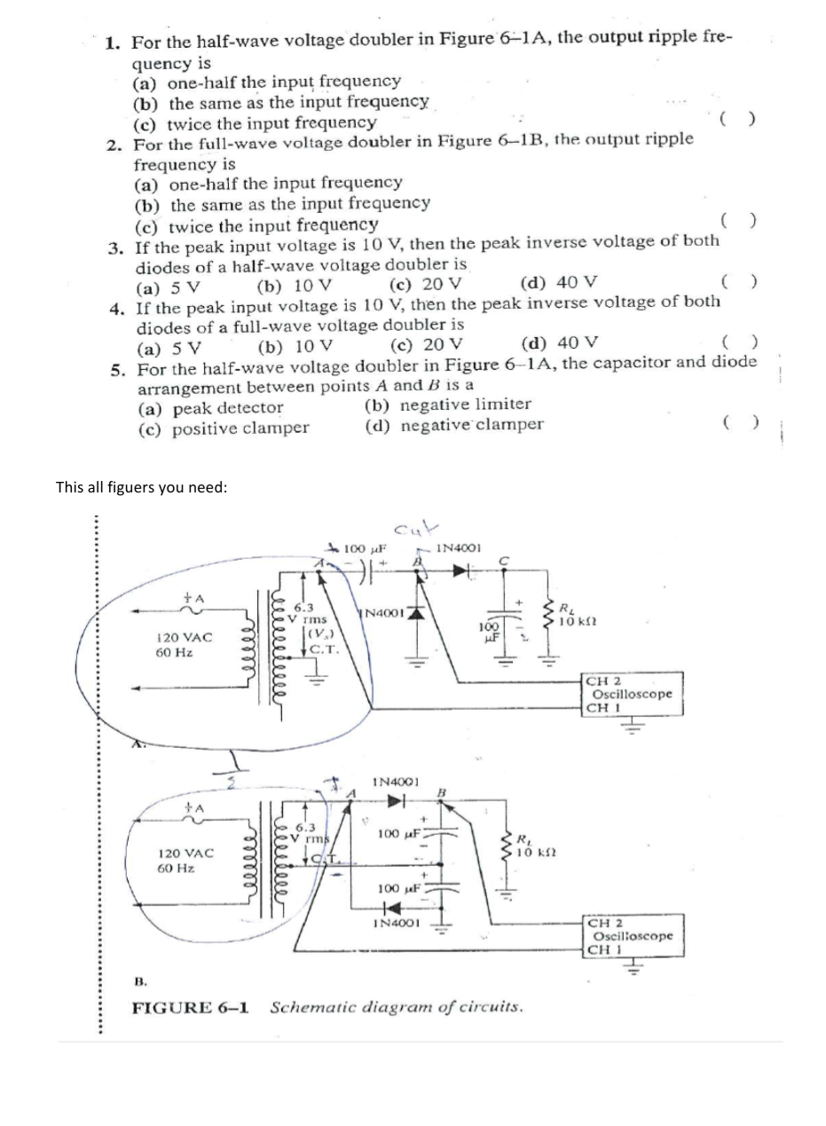
1. For the half-wave voltage doubler in Figure 6–1A, the output ripple fre- quency is (a) one-half the inpuț frequency (b) the same as the input frequency (c) twice the input frequency 2. For the full-wave voltage doubler in Figure 6–1RB, the output ripple frequency is (a) one-half the input frequency (b) the same as the input frequency (c) twice the input frequency 3. If the peak input voltage is 10 V, then the peak inverse voltage of both diodes of a half-wave voltage doubler is (b) 10 V (c) 20 V (d) 40 V (а) 5 V 4. If the peak input voltage is 10 V, then the peak inverse voltage of both diodes of a full-wave voltage doubler is (a) 5 V 5. For the half-wave voltage doubler in Figure 6–1A, the capacitor and diode arrangement between points A and B is a (a) peak detector (c) positive clamper (b) 10 V (c) 20 V (d) 40 V (b) negative limiter (d) negative clamper is all figuers you need: Cut - IN4001 A 100 uF 6.3 V rms N4001 RL 10 kl2 120 VAC 60 Hz С.Т. CH 2 Oscilloscope CH I IN4001 6.3 V rms 100 µF S10 k 120 VAC 60 Hz 100 helll سنیش
1. For the half-wave voltage doubler in Figure 6–1A, the output ripple fre- quency is (a) one-half the inpuț frequency (b) the same as the input frequency (c) twice the input frequency 2. For the full-wave voltage doubler in Figure 6–1RB, the output ripple frequency is (a) one-half the input frequency (b) the same as the input frequency (c) twice the input frequency 3. If the peak input voltage is 10 V, then the peak inverse voltage of both diodes of a half-wave voltage doubler is (b) 10 V (c) 20 V (d) 40 V (а) 5 V 4. If the peak input voltage is 10 V, then the peak inverse voltage of both diodes of a full-wave voltage doubler is (a) 5 V 5. For the half-wave voltage doubler in Figure 6–1A, the capacitor and diode arrangement between points A and B is a (a) peak detector (c) positive clamper (b) 10 V (c) 20 V (d) 40 V (b) negative limiter (d) negative clamper is all figuers you need: Cut - IN4001 A 100 uF 6.3 V rms N4001 RL 10 kl2 120 VAC 60 Hz С.Т. CH 2 Oscilloscope CH I IN4001 6.3 V rms 100 µF S10 k 120 VAC 60 Hz 100 helll سنیش

Delmar's Standard Textbook Of Electricity
7th Edition
ISBN:9781337900348
Author:Stephen L. Herman
Publisher:Stephen L. Herman
Chapter14: Basic Trigonometry And Vectors
Section: Chapter Questions
Problem 5RQ: 5. The hypotenuse has a length of 65 in., and side A has a length of 31 in. What is angle X?

Related questions

Question
100%
This multiple choice questions from electronics lab,please solve all i think it's easy for you and good luck in your life.??
Transcribed Image Text:1. For the half-wave voltage doubler in Figure 6–1A, the output ripple fre-
quency is
(a) one-half the input frequency
(b) the same as the input frequency
(c) twice the input frequency
2. For the full-wave voltage doubler in Figure 6–1B, the output ripple
frequency is
(a) one-half the input frequency
(b) the same as the input frequency
(c) twice the input frequency
3. If the peak input voltage is 10 V, then the peak inverse voltage of both
diodes of a half-wave voltage doubler is
(а) 5 V
4. If the peak input voltage is 10 V, then the peak inverse voltage of both
diodes of a full-wave voltage doubler is
(a) 5 V
5. For the half-wave voltage doubler in Figure 6–1A, the capacitor and diode
arrangement between points A and B is a
(a) peak detector
(c) positive clamper
(b) 10 V
(c) 20 V
(d) 40 V
(b) 10 V
(c) 20 V
(d) 40 V
(b) negative limiter
(d) negative clamper
This all figuers you need:
cut
- IN4001
100 µF
+A
6.3
N4001
rms
10 k?
100
120 VAC
60 Hz
С.Т.
CH 2
Oscilloscope
CH 1
IN4001
6.3
V rms
100 uF
10 k2
120 VAC
60 Hz
100 uF
CH 2
Oscilioscope
CH 1
IN4001
B.
FIGURE 6-1
Schematic diagram of circuits.
reilletee
ع منيفق
ellle
Expert Solution
This question has been solved!
Explore an expertly crafted, step-by-step solution for a thorough understanding of key concepts.

Step by step
Solved in 2 steps with 2 images

Knowledge Booster


Learn more about
Need a deep-dive on the concept behind this application? Look no further. Learn more about this topic, electrical-engineering and related others by exploring similar questions and additional content below.Recommended textbooks for you
Delmar's Standard Textbook Of Electricity
Electrical Engineering
ISBN:
9781337900348
Author:
Stephen L. Herman
Publisher:
Cengage Learning
Delmar's Standard Textbook Of Electricity
Electrical Engineering
ISBN:
9781337900348
Author:
Stephen L. Herman
Publisher:
Cengage Learning