1. How great is the number of pulses in the three - phase half-wave rectifier?
1. How great is the number of pulses in the three - phase half-wave rectifier?

Introductory Circuit Analysis (13th Edition)
13th Edition
ISBN:9780133923605
Author:Robert L. Boylestad
Publisher:Robert L. Boylestad
Chapter1: Introduction
Section: Chapter Questions
Problem 1P: Visit your local library (at school or home) and describe the extent to which it provides literature...

Related questions
Question
please answer this question for the the for this report
Q) how great is the number of pulses in a three-phase half-wave rectifier
Transcribed Image Text:El . EO M1
36
151+7:13
2_5422347806918580582 - Read-only
ビy
Read Only - You can't save changes to...
Power Electronics Lab.
Experiment No. 6
جامعة بغداد كلية هندسة الخوارزمی
قسم هندسة الميكاترونكس
مختير ألكترونيات القدرة
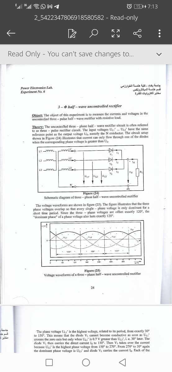
3-0 half – wave uncontrolled rectifier
Object: The object of this experiment is to measure the currents and voltages in the
uncontrolled three- pulse half- wave rectifier with resistive load.
Theory: The uncontrolled three - phase half - wave rectifier circuit is often referred
to as three - pulse rectifier circuit. The input voltages UL' . ULs' have the same
reference point as the output voitage Ug, namely the N conductor. The circuit setup
shown in Figure (24) illustrates that current can only flow through one of the diodes
when the corresponding phase voltage is greater than Ua.
L1 -mmm
中
L2 mm m
V3
L3 m m
Is
Vs
RL
ULT V2
ULS
Figure (24)
Schematic diagram of three - phase half-wave uncontrolled rectifier
The voltage waveforms are shown in figure (25). The figure illustrates that the three
phase voltages overlap so that every single - phase voltage is only dominant for a
short time period. Since the three - phase voltages are offset exactly 120°, the
"dominant phase" of a phase voltage also lasts exactly 120°.
ULT
- 120 .
- 120
120
30
129
180
Figure (25)
Voltage waveforms of a three - phase half- wave uncontrolled rectifier
24
جامعة
The phase voltage Uu' is the highest voltage, related to its period, from exactly 30°
to 150°. This means that the diode Vj cannot become conductive as soon as ULI'
crosses the zero axis but only when ULI' is 0.7 V greater than ULs', i. e. 30° later. The
diode Vj then carries the direct current L, to 150°. Then Vs takes over the current
because UL2' is the highest phase voltage from 150° to 270°. From 270° to 30° again
the dominant phase voltage is ULa' and diode V, carries the current Ia. Each of the
مختبر -
Transcribed Image Text:O 161+ 7:15
3G
36
2_5422347806918580582 - Read-only
Read Only - You can't save changes to...
The phase voltage ULI' is the highest voltage, related to its period, from exactly 30°
to 150°. This means that the diode Vi cannot become conductive as soon as ULI'
crosses the zero axis but only when ULI' is 0.7 V greater than ULs', i. e. 30° later. The
diode V, then carries the direct current Ig to 150°. Then V; takes over the current
because UL2' is the highest phase voltage from 150° to 270°. From 270° to 30° again
the dominant phase voltage is ULs' and diode Vs carries the current Ig. Each of the
diodes therefore carries the current for a third of the period duration. When a diode
takes over the current, this is known as commutation. We say that the current
commutates from V, to V3 at 150e.
مختير -
Necessary equipments:
1. Рower Board (Турс 5125).
2. 1 standard Oscilloscope with the possibility of internal triggering with the
LINE trigger source.
3. 1 digital multimeter with the possibility of measuring ms values
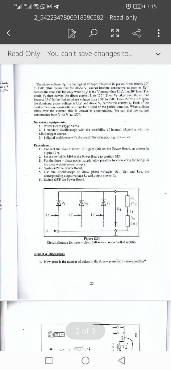
Procedure:
1. Connect the circuit shown in Figure (26) on the Power Board, as shown in
Figure (27).
2. Set the switch M3/B6 at the Power Board to position M3.
3. Put the three - phase power supply into operation by connecting the bridge in
the three - phase power supply.
4. Switch ON the Power Board.
5. Use the Oscilloscope to draw phase voltages ULI. UL2 and UL3, the
corresponding output voltage Ua and output current Ig.
6.. Switch OFF the Power Board.
RL
AVs
27
L1'
L2'
L3'
Re
0.50
Figure (26)
Circuit diagrum for three - phase half- wave uncontrolled rectifier
Report & Discussion:
1. How great is the number of pulses in the three - phase half - wave rectifier?
25
2 of 3
Expert Solution
This question has been solved!
Explore an expertly crafted, step-by-step solution for a thorough understanding of key concepts.

Step by step
Solved in 2 steps with 1 images

Knowledge Booster


Learn more about
Need a deep-dive on the concept behind this application? Look no further. Learn more about this topic, electrical-engineering and related others by exploring similar questions and additional content below.Recommended textbooks for you
Introductory Circuit Analysis (13th Edition)
Electrical Engineering
ISBN:
9780133923605
Author:
Robert L. Boylestad
Publisher:
PEARSON

Delmar's Standard Textbook Of Electricity
Electrical Engineering
ISBN:
9781337900348
Author:
Stephen L. Herman
Publisher:
Cengage Learning

Programmable Logic Controllers
Electrical Engineering
ISBN:
9780073373843
Author:
Frank D. Petruzella
Publisher:
McGraw-Hill Education
Introductory Circuit Analysis (13th Edition)
Electrical Engineering
ISBN:
9780133923605
Author:
Robert L. Boylestad
Publisher:
PEARSON
Delmar's Standard Textbook Of Electricity
Electrical Engineering
ISBN:
9781337900348
Author:
Stephen L. Herman
Publisher:
Cengage Learning
Programmable Logic Controllers
Electrical Engineering
ISBN:
9780073373843
Author:
Frank D. Petruzella
Publisher:
McGraw-Hill Education

Fundamentals of Electric Circuits
Electrical Engineering
ISBN:
9780078028229
Author:
Charles K Alexander, Matthew Sadiku
Publisher:
McGraw-Hill Education

Electric Circuits. (11th Edition)
Electrical Engineering
ISBN:
9780134746968
Author:
James W. Nilsson, Susan Riedel
Publisher:
PEARSON

Engineering Electromagnetics
Electrical Engineering
ISBN:
9780078028151
Author:
Hayt, William H. (william Hart), Jr, BUCK, John A.
Publisher:
Mcgraw-hill Education,