1. Resistance Measurement Choose a 10% (or a 5% tolerance if you don't have a 10%) tolerance resistors from your kit. Use the color bands on the resistor body to determine its rating. Use the analog multimeter to measure the resistance of the device. Trial | Analog Multimeter Resistance Measurement (N) 1 35 2 35 3 35 Average 35 Resistance rating Percentage Error Use the formula %error = - x 100 Is the measured value of resistance within the allotted tolerance?
1. Resistance Measurement Choose a 10% (or a 5% tolerance if you don't have a 10%) tolerance resistors from your kit. Use the color bands on the resistor body to determine its rating. Use the analog multimeter to measure the resistance of the device. Trial | Analog Multimeter Resistance Measurement (N) 1 35 2 35 3 35 Average 35 Resistance rating Percentage Error Use the formula %error = - x 100 Is the measured value of resistance within the allotted tolerance?

Introductory Circuit Analysis (13th Edition)
13th Edition
ISBN:9780133923605
Author:Robert L. Boylestad
Publisher:Robert L. Boylestad
Chapter1: Introduction
Section: Chapter Questions
Problem 1P: Visit your local library (at school or home) and describe the extent to which it provides literature...

Related questions
Question
1.1 Please solve and explain.
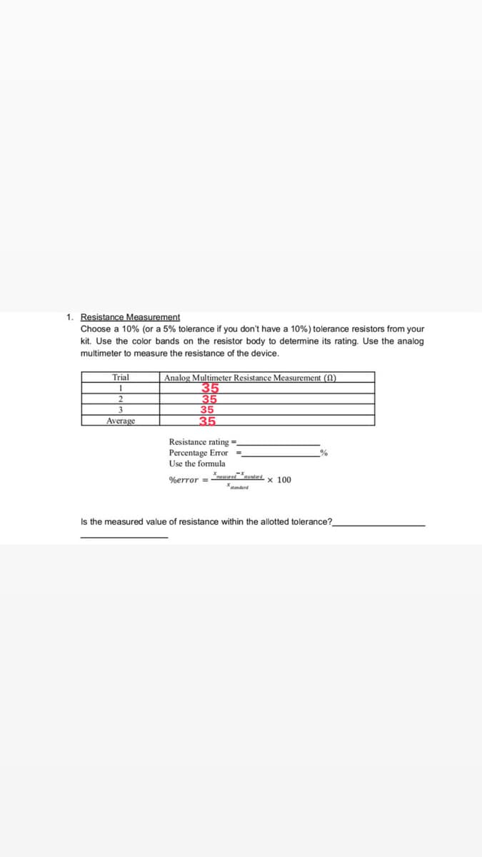
Transcribed Image Text:1. Resistance Measurement
Choose a 10% (or a 5% tolerance if you don't have a 10%) tolerance resistors from your
kit. Use the color bands on the resistor body to determine its rating. Use the analog
multimeter to measure the resistance of the device.
Analog Multimeter Resistance Measurement
Trial
1
35
35
3
35
Average
35
Resistance rating=_
%
Percentage Error =_
Use the formula
measured standard
%error =
x 100
Is the measured value of resistance within the allotted tolerance?
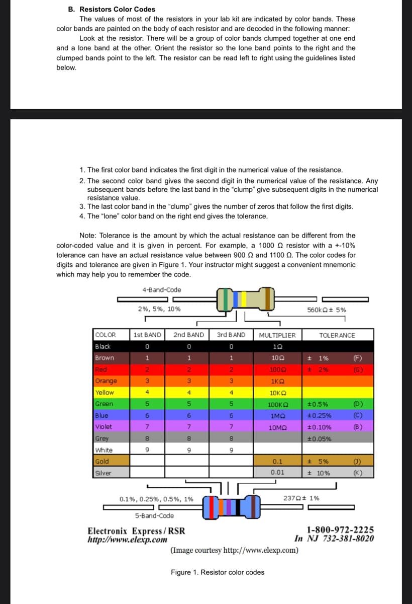
Transcribed Image Text:B. Resistors Color Codes
The values of most of the resistors in your lab kit are indicated by color bands. These
color bands are painted on the body of each resistor and are decoded in the following manner:
Look at the resistor. There will be a group of color bands clumped together at one end
and a lone band at the other. Orient the resistor so the lone band points to the right and the
clumped bands point to the left. The resistor can be read left to right using the guidelines listed
below.
1. The first color band indicates the first digit in the numerical value of the resistance.
2. The second color band gives the second digit in the numerical value of the resistance. Any
subsequent bands before the last band in the "clump" give subsequent digits in the numerical
resistance value.
3. The last color band in the "clump" gives the number of zeros that follow the first digits.
4. The "lone" color band on the right end gives the tolerance.
Note: Tolerance is the amount by which the actual resistance can be different from the
color-coded value and it is given in percent. For example, a 1000 resistor with a +-10%
tolerance can have an actual resistance value between 900 22 and 1100 2. The color codes for
digits and tolerance are given in Figure 1. Your instructor might suggest a convenient mnemonic
which may help you to remember the code.
4-Band-Code
N
2%, 5%, 10%
560kQ+ 5%
1st BAND
COLOR
Black
0
Brown
1
Red
2
Orange
3
Yellow
4
Green
5
Blue
6
Violet
7
Grey
8
White
9
Gold
Silver
0.1%, 0.25%, 0.5%, 1%
5-Band-Code
Electronix Express/RSR
http://www.elexp.com
2nd BAND
0
1
2
3
4
5
6
7
8
9
3rd BAND
0
1
2
3
4
5
6
7
8
9
חוה
MULTIPLIER
10
10Q2
1000
1KQ
10KQ
100ΚΩ
1MQ
10ΜΩ
0.1
0.01
TOLERANCE
(F)
(G)
(D)
(B)
(1)
(K)
1-800-972-2225
In NJ 732-381-8020
01
(Image courtesy http://www.elexp.com)
Figure 1. Resistor color codes
± 1%
± 2%
±0.5%
+0.25%
±0.10%
±0.05%
± 5%
± 10%
2370+ 1%
Expert Solution
This question has been solved!
Explore an expertly crafted, step-by-step solution for a thorough understanding of key concepts.

Step by step
Solved in 2 steps

Knowledge Booster


Learn more about
Need a deep-dive on the concept behind this application? Look no further. Learn more about this topic, electrical-engineering and related others by exploring similar questions and additional content below.Recommended textbooks for you
Introductory Circuit Analysis (13th Edition)
Electrical Engineering
ISBN:
9780133923605
Author:
Robert L. Boylestad
Publisher:
PEARSON

Delmar's Standard Textbook Of Electricity
Electrical Engineering
ISBN:
9781337900348
Author:
Stephen L. Herman
Publisher:
Cengage Learning

Programmable Logic Controllers
Electrical Engineering
ISBN:
9780073373843
Author:
Frank D. Petruzella
Publisher:
McGraw-Hill Education
Introductory Circuit Analysis (13th Edition)
Electrical Engineering
ISBN:
9780133923605
Author:
Robert L. Boylestad
Publisher:
PEARSON
Delmar's Standard Textbook Of Electricity
Electrical Engineering
ISBN:
9781337900348
Author:
Stephen L. Herman
Publisher:
Cengage Learning
Programmable Logic Controllers
Electrical Engineering
ISBN:
9780073373843
Author:
Frank D. Petruzella
Publisher:
McGraw-Hill Education

Fundamentals of Electric Circuits
Electrical Engineering
ISBN:
9780078028229
Author:
Charles K Alexander, Matthew Sadiku
Publisher:
McGraw-Hill Education

Electric Circuits. (11th Edition)
Electrical Engineering
ISBN:
9780134746968
Author:
James W. Nilsson, Susan Riedel
Publisher:
PEARSON

Engineering Electromagnetics
Electrical Engineering
ISBN:
9780078028151
Author:
Hayt, William H. (william Hart), Jr, BUCK, John A.
Publisher:
Mcgraw-hill Education,