1. What is the output voltage that you would expect to observe across RL in the clamping circuit of figure B-1? Assume that RC is large enough to prevent significant capacitor discharge. +24 V 10 uF V ov R 10 kn IN4001 -24 V
1. What is the output voltage that you would expect to observe across RL in the clamping circuit of figure B-1? Assume that RC is large enough to prevent significant capacitor discharge. +24 V 10 uF V ov R 10 kn IN4001 -24 V

Delmar's Standard Textbook Of Electricity
7th Edition
ISBN:9781337900348
Author:Stephen L. Herman
Publisher:Stephen L. Herman
Chapter19: Capacitors
Section: Chapter Questions
Problem 2PA: You are an electrician working in an industrial plant. You discover that the problem with a certain...

Related questions
Question
Please help solve
Transcribed Image Text:8:24
ull LTE 4
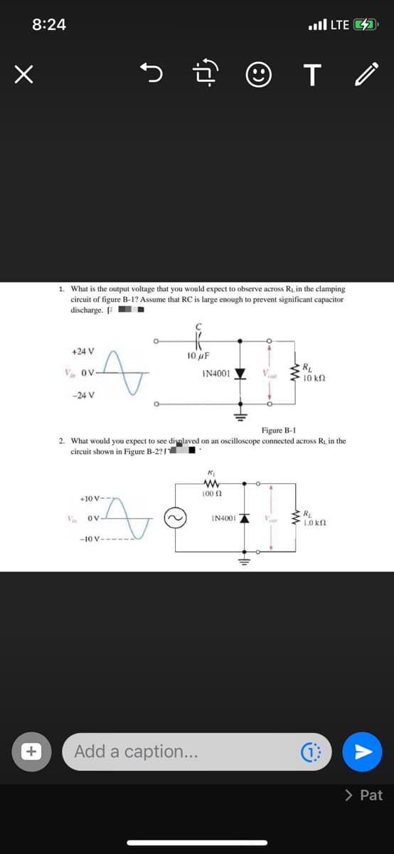
1. What is the output voltage that you would expect to observe across RL in the clamping
circuit of figure B-1? Assume that RC is large enough to prevent significant capacitor
discharge. [ .
+24 V
10 uF
V Ov
IN4001
10 k
-24 V
Figure B-1
2. What would you expect to see disnlaved on an oscilloscope connected across Ri, in the
circuit shown in Figure B-2? TI
100 n
+10 V-
V
Ov-
IN4001
1.0 kn
-10 V--
Add a caption...
> Pat
+
Transcribed Image Text:8:23
ull LTE 4
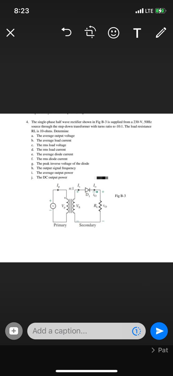
4. The single-phase half wave rectifier shown in Fig B-3 is supplied from a 230-V, 50HZ
source through the step-down transformer with turns ratio n=10:1. The load resistance
RL is 10-ohms, Determine
a. The average output voltage
b. The average load current
c. The rms load voltage
d. The rms load current
e. The average diode current
f. The rms diode current
g. The peak inverse voltage of the diode
h. The output signal frequency
i. The average output power
j. The DC output power
n:1
Fig B-3
R
Vo
Primary
Secondary
Add a caption...
> Pat
+
Expert Solution
This question has been solved!
Explore an expertly crafted, step-by-step solution for a thorough understanding of key concepts.

This is a popular solution!

Trending now
This is a popular solution!

Step by step
Solved in 3 steps with 3 images

Recommended textbooks for you
Delmar's Standard Textbook Of Electricity
Electrical Engineering
ISBN:
9781337900348
Author:
Stephen L. Herman
Publisher:
Cengage Learning
Delmar's Standard Textbook Of Electricity
Electrical Engineering
ISBN:
9781337900348
Author:
Stephen L. Herman
Publisher:
Cengage Learning