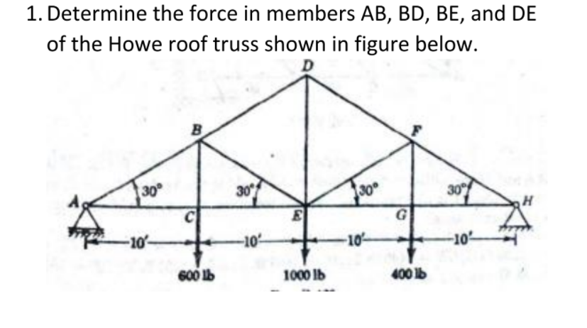
1.Determine the force in members AB, BD, BE, and DE of the Howe roof truss shown in figure below. 600lb, 1000lb, 400lb


Q: Question-4 Find the magnitude and nature of the forces in members AC, AD, DB, CE, CF and FD by…
A: Calculating reaction forces at support G and H: ∑Fx=0RG+1=0HG=-1 KN∑Fy=0RG+RH=2
Q: For the truss shown in the figure determine the forces in members HD, HI and AD. G 4 KN 8 m 4 kN H E…
A:
Q: Problem 4: Determine the forces in members GF, CD, and GC. State if the members are in tension or…
A: Given that...
Q: Determine the force in the members LP and EF of the truss shown in Fig. (4). 10 kN- 10 m 20 kN AJ 10…
A: Finding out forces in member LP and EF.
Q: Fig. P.4.16 shows the plan of a space truss which consists of six pin-jointed members. The member DE…
A:
Q: Example 3: Determine the forces in members BC and BG of the loaded truss. 3 kN 3 kN 2m C 2 m 2m 2m 2…
A:
Q: A 1.0 m 2.0 m E 100 kN 2.0 m 1.0m D 4.5 m
A:
Q: 600 lb Determine the forces in A all members of the truss 300 lb 300 lb as well as the forces 6 ft…
A:
Q: FIGURE 1 60 kN Height 0.75 :1.00 1.00. 1.00 C00 25 kN
A:
Q: Problem 5. Find member forces and reactions for the truss with loads shown. 800 N 600 N D 500 N B 2m…
A: Given Problem :
Q: Problme (1) : Determine the force in each members of the truss shown in Figure (1) by using method…
A: In the method of joint, we have to analyze all joints using an equilibrium equation. In this method,…
Q: 1. Analyze the truss arch shown. Determine the reactions at the supports and the bar forces of…
A:
Q: Determine the stability and determinacy of the truss shown in Figure 1. b) Use the method of…
A: Using section method
Q: Determine the forces in DF, EF, and EG in the truss shown diagrammatically in the figure. 40 kN 40…
A: Force can be taken as tension when force is away from joint Force can be taken as compression when…
Q: 30 kN 50 kN 40 kN to to D 20 kN 4 m HẠ+ 30 kN 4 m 4 m Figure: 3a and 3b
A:
Q: Determine the forces in member BE of the Howe roof truss shown in lbs. P1 = 364 kN and P2 = 646 kN.…
A: Given data in question Truss Dimensions Point loads To find out Force in member BE. Note We will…
Q: Find the magnitude and nature of the forces in all the members of the given truss. Figure: 3a
A: Solution: "Since you have asked multiple questions, we will solve the first question for you. If you…
Q: EXAMPLE 4.5.1 Determine the force in cach member of the truss shown in the Fig. 4.5.5 and indicate…
A:
Q: or the truss shown below, determine the magnitude of forces in members CD, CE and DE. Also, identify…
A: Draw free body diagram From above figure tan θ=1.53θ=tan-10.5θ=26.56o Draw free body diagram of…
Q: For the truss shown in the figure determine the forces in members HD, HI and AD. F G 4 kN 8 m 4 kN H…
A:
Q: HW3: For the truss shown in Fig.3, compute the maximum axial forces that can be developed in members…
A: The axial load or force operating through the centroid or geometric axis of a structure is defined…
Q: Q2. Determine the force in each member of the double-pitch roof truss as shown in Fig.2. State…
A: ∈Fx=0HA=0∈MH=0RA×18-1×18-2×14-2×10-6×1.75-1.5×3=0RA×18=81RA=4.5KN∈Fy=0RA+RH=1+2+2+1.75+1.5+0.75RH=4.…
Q: Q2: Classify the truss shown in Fig.(2) and find the bar forces BD and BG. 20 kN 10 kN +F G. 6m B 2m…
A:
Q: Calculate all the forces in the truss shown, indicate if the member is in tension or compression.…
A: Given Data: Given a truss and asked to find all the forces in the members. here, Truss is analysed…
Q: ate all the member forces in the given truss using method of consistent deformation. Joint D is…
A: Given:- F=4450kN L=8m To find:- Member Forces
Q: As Engineer, you have been asked to calculate only the forces in the members (AB, AC, BC, and CE) of…
A:
Q: Calculate the forces induced in members KL, CL, and CB by the 20-ton load on the cantilever truss
A: Calculate the forces induced in members KL, CL, and CB by the 20-ton load on the cantilever truss
Q: 7. Determine the force in members CD, CJ, KJ, and DJ of the truss which serves to support the deck…
A:
Q: The truss is loaded by two concentrated forces as shown in the figure. Use E = 30 x 106 psi and A =…
A: Deformation in bars can be calculated by determining force carried by those bars and then…
Q: A Mansard roof truss is loaded as shown. Determine the force in members DG in kN. P = 2.5 kN and x =…
A:
Q: Problem No. 1. Determine all the forces acting on the structure shown. Also, indicate the type of…
A: Determine all the forces acting on the structure shown. Also, indicate the type of force acting on…
Q: Find the concentrated loads equivalent to the parabolic, triangular and trapezoidal distributed…
A: Drawing the FBD of the Beam structure:
Q: Situation 2 Find the following forces in members of the transmission line truss shown in figu…
A:
Q: EXAMPLE 4.5.1 Determine the force in cach member of the truss shown in the Fig. 4.5.5 and indicate…
A:
Q: tant, its inclination with the horizontal, and where it intersects AB.
A: Draw the free body diagram Consider the summation of forces in the horizontal direction…
Q: The truss shown in the figure is applied with force P = 5 KN. 1.50 m 1.50 m 1.50 m P B 2 m 2 m 1.…
A: Method of joints: In this method, a joint is isolated by considering all the forces acting at that…
Q: Determine the support reactions for the truss loaded with uniform wind load shown.
A: The truss is the member that it has member which connect triangle that over all assembly act like…
Q: Determine the force in each member of the truss shown. Tabulate the results. Indicate the nature. 20…
A:
Q: QUESTION 2 Determine the force in members CE, CD and AD and state whether the members are in tension…
A:
Q: Determine the force in each member of the Pratt roof truss shown in the image. The 1000 lb loads…
A: As we know that the resultant force: R=∈fx2+fy2∅=tan-138∅=20.55Consider the 90-∅=90-20.55…
Q: members of the truss have the same length L=4.4 m. Determine the MAGNITUDE (N) of force supported by…
A:
Q: Question-4 Find the magnitude and nature of the forces in members AC, AD, DB, CE, CF and FD by…
A: The given data is: Load at B (horizontal) = 1 kN Load at B (vertical) = 2 kN
Q: The portion of truss shown represents the upper part of a power transmission line tower. For the…
A:
Q: Problem No. 1. Determine all the forces acting on the structure shown. Also, indicate the type of…
A:
Q: Problem No. 1. Determine all the forces acting on the structure shown. Also, indicate the type of…
A: Determine all the forces acting on the structure shown.
Q: Q3/ 1.Determine the type of the truss in Fig.(3) 2.If the truss is made of a material has maximum…
A: Determine the largest load P can be applied to that truss?
Q: The truss shown in the figure is applied with force P = 5 KN. A. Which of the following nearly…
A: The method of joints is a process used to solve for the unknown forces acting on members of a truss.…
Q: determine the force in member BD of the truss shown. State whether each member is in tension or…
A:
Q: 1.18 Determine the smallest safe cross-sectional areas of members CD, GD, and GF for the truss…
A:
1.Determine the force in members AB, BD, BE, and DE of the Howe roof truss shown in figure below. 600lb, 1000lb, 400lb


Trending now
This is a popular solution!

Step by step
Solved in 3 steps with 3 images


- A howe truss has six panels and each panel is 1m. The span is 6m and height 1.50m. Joints U1, U2, U3, U4, and U5 each carry a vertical full panel load PL = 2600lb and joints L0 and L6 each carry a vertical half panel load PL/2 = 1300lb. Find the value of maximum tensile stress of such member.Calculate the area A of the A36 steel truss member by , where Fmax is the highest load in the truss members,For the given Bollman Bridge truss assembly shown in Figure 1and using the information given in Table 1, determine the internal forces acting along BC, EC and EHusing sectioning method if the point A is a roller support and point G is pin support. Also mention if the members are in tension or in compression.
- A Mansard roof truss is loaded as shown. Determing the force in members EG in kN. P = 6.5 kN and x = 4.7 m. Write numerical value and in two decimal places.What is ϕMn for W8x24 - A36 steel in lb-ft for: a) 15 ft b) 30 ftA Howe scissors roof truss is shown. A Howe scissors roof truss is loaded as shown. Determine the force in members Gl, Hl, and HJ when P1 = 1 kips and P2 = 2 kips. Note: please double check your answers!. Thanks
- 22 A concrete floor slab 100 mm thick is cast monolithic with concrete beams 2.0 m on centers. The beams have a span of 4 m and have a web width of 250 mm, an effective depth of 400 mm and overall depth of 500 mm. The tensile reinforcement consists of 6-ϕ32 mm bars in two rows. Use material strengths f’c = 21 MPa and fy = 415 MPa. Calculate the ultimate bending moment strength of the T-beam in kN·m. 640 778 711 701A howe truss has six panels and each panel is 1m. The span is 6m and height 1.50m. Joints U1, U2, U3, U4, and U5 each carry a vertical full panel load PL = 2600lb and joints L0 and L6 each carry a vertical half panel load PL/2 = 1300lb. Find the value of the stress of member L2L3.Three bars, AB, AC, and AD, are pinned together to support a load P = 20 kN as shown in Fig. P-256. Horizontal movement is prevented at joint A by the short horizontal strut AE. Determine the stress in each bar and the force in the strut AE. For the steel bar, A = 200 mm and E=200 GPa. For each aluminum bar, A=400 mm^2 and E= 70 GPa.
- W 14 x 142 is used as a column having a length of 8.48 m. long. It is hinged at the r end and fixed at the lower end but there is a lateral bracing perpendicular to minor axis of the W section at a point 4.78 m. above the bottom support. It is assumed to be pinned connected at the bracing point. Using A 36 steel Fy= 248 MPa the NSCP Specificatioris. E, = 200000 MPa. Properties of W 14 x 142 A = 26967.69 mm2 d= 374.65 mm bf= 393.70 mm tf= 27.00 mm tw= 17.27 mm4 Ix= 695.11 x 106 mm4 Iy = 274.71 x 106 mm4 rx = 160.53 mm rY = 100.84 mm Assume: Kx = 0.80 for 8.48 m. length KY = 1.9 for the length on the upper support KY = 0.80 for the length on the bottom support Compute the slenderness ratio along y-axis.W 14 x 142 is used as a column having a length of 8.48 m. long. It is hinged at the r end and fixed at the lower end but there is a lateral bracing perpendicular to minor axis of the W section at a point 4.78 m. above the bottom support. It is assumed to be pinned connected at the bracing point. Using A 36 steel Fy= 248 MPa the NSCP Specificatioris. E, = 200000 MPa. Properties of W 14 x 142 A = 26967.69 mm2 d= 374.65 mm bf= 393.70 mm tf= 27.00 mm tw= 17.27 mm4 Ix= 695.11 x 106 mm4 Iy = 274.71 x 106 mm4 rx = 160.53 mm rY = 100.84 mm Assume: Kx = 0.80 for 8.48 m. length KY = 1.9 for the length on the upper support KY = 0.80 for the length on the bottom support Compute the slenderness ratio along y-axis. Please show clear solution thank youCalculate for the cross-section of members AG, BC, and CE for the truss assembly shown in the figure below, considering that the stresses are not to exceed 20 ksi categorized in tension and 14 ksi categorized in compression. NOTE: A reduced stress in compression is specified to reduce the danger of buckling.