10 10 μα R1 100 Ω | SNSPD L 100 nH R2 2ΜΩ S V 1. No photons have been incident on the detector for a long time, and thus the switch has bee closed for t <0 as shown in the figure. Find i, (0) and vs (07).
10 10 μα R1 100 Ω | SNSPD L 100 nH R2 2ΜΩ S V 1. No photons have been incident on the detector for a long time, and thus the switch has bee closed for t <0 as shown in the figure. Find i, (0) and vs (07).

Introductory Circuit Analysis (13th Edition)
13th Edition
ISBN:9780133923605
Author:Robert L. Boylestad
Publisher:Robert L. Boylestad
Chapter1: Introduction
Section: Chapter Questions
Problem 1P: Visit your local library (at school or home) and describe the extent to which it provides literature...

Related questions

Question
Handwrite, step by step solutions
Transcribed Image Text:Superconducting nanowire single-photon detectors (SNSPDs) are extremely sensitive devices that
can detect individual particles of light, called photons, with nearly 100% detection efficiency. They
were invented about 20 years ago and have become the world's fastest and most efficient detectors
for low-light applications, such as quantum communications and computing, lidar, and astronomy.
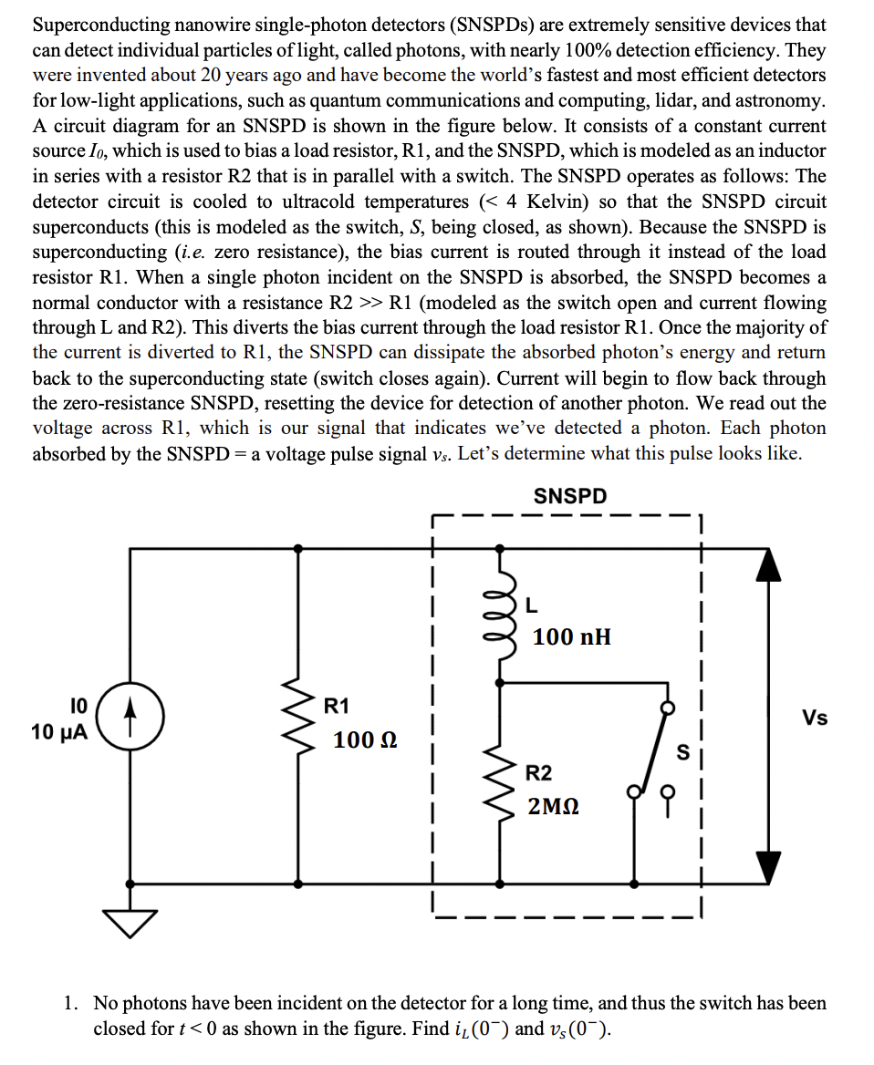
A circuit diagram for an SNSPD is shown in the figure below. It consists of a constant current
source Io, which is used to bias a load resistor, R1, and the SNSPD, which is modeled as an inductor
in series with a resistor R2 that is in parallel with a switch. The SNSPD operates as follows: The
detector circuit is cooled to ultracold temperatures (< 4 Kelvin) so that the SNSPD circuit
superconducts (this is modeled as the switch, S, being closed, as shown). Because the SNSPD is
superconducting (i.e. zero resistance), the bias current is routed through it instead of the load
resistor R1. When a single photon incident on the SNSPD is absorbed, the SNSPD becomes a
normal conductor with a resistance R2 >> R1 (modeled as the switch open and current flowing
through L and R2). This diverts the bias current through the load resistor R1. Once the majority of
the current is diverted to R1, the SNSPD can dissipate the absorbed photon's energy and return
back to the superconducting state (switch closes again). Current will begin to flow back through
the zero-resistance SNSPD, resetting the device for detection of another photon. We read out the
voltage across R1, which is our signal that indicates we've detected a photon. Each photon
absorbed by the SNSPD = a voltage pulse signal vs. Let's determine what this pulse looks like.
SNSPD
10
10 μα
ww
R1
100 Ω
mm
L
100 nH
R2
2ΜΩ
0
Vs
1. No photons have been incident on the detector for a long time, and thus the switch has been
closed for t<0 as shown in the figure. Find i₁(0¯) and vs (0¯).
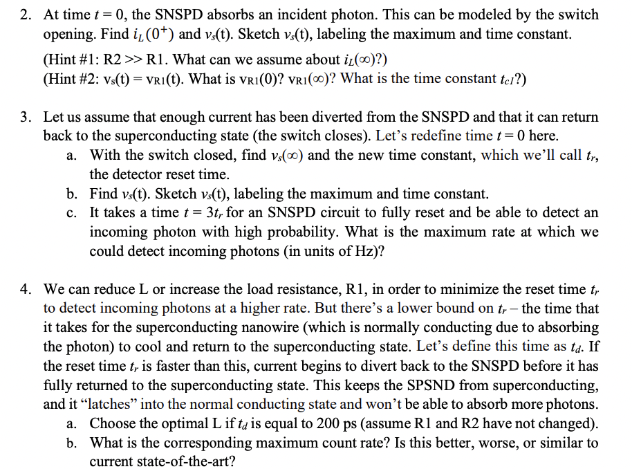
Transcribed Image Text:2. At time t = 0, the SNSPD absorbs an incident photon. This can be modeled by the switch
opening. Find i, (0+) and vs(t). Sketch vs(t), labeling the maximum and time constant.
(Hint #1: R2 >> R1. What can we assume about it()?)
(Hint #2: Vs(t) = VRI(t). What is VR1(0)? VR1(0)? What is the time constant tel?)
3. Let us assume that enough current has been diverted from the SNSPD and that it can return
back to the superconducting state (the switch closes). Let's redefine time t = 0 here.
With the switch closed, find vs(oo) and the new time constant, which we'll call tr,
the detector reset time.
b.
Find vs(t). Sketch vs(t), labeling the maximum and time constant.
c. It takes a time t = 3tr for an SNSPD circuit to fully reset and be able to detect an
incoming photon with high probability. What is the maximum rate at which we
could detect incoming photons (in units of Hz)?
4. We can reduce L or increase the load resistance, R1, in order to minimize the reset time tr
to detect incoming photons at a higher rate. But there's a lower bound on tr- the time that
it takes for the superconducting nanowire (which is normally conducting due to absorbing
the photon) to cool and return to the superconducting state. Let's define this time as td. If
the reset time t, is faster than this, current begins to divert back to the SNSPD before it has
fully returned to the superconducting state. This keeps the SPSND from superconducting,
and it "latches" into the normal conducting state and won't be able to absorb more photons.
a. Choose the optimal L if ta is equal to 200 ps (assume R1 and R2 have not changed).
b. What is the corresponding maximum count rate? Is this better, worse, or similar to
current state-of-the-art?
Expert Solution
This question has been solved!
Explore an expertly crafted, step-by-step solution for a thorough understanding of key concepts.

This is a popular solution!

Trending now
This is a popular solution!

Step by step
Solved in 6 steps with 5 images

Knowledge Booster


Learn more about
Need a deep-dive on the concept behind this application? Look no further. Learn more about this topic, electrical-engineering and related others by exploring similar questions and additional content below.Recommended textbooks for you
Introductory Circuit Analysis (13th Edition)
Electrical Engineering
ISBN:
9780133923605
Author:
Robert L. Boylestad
Publisher:
PEARSON

Delmar's Standard Textbook Of Electricity
Electrical Engineering
ISBN:
9781337900348
Author:
Stephen L. Herman
Publisher:
Cengage Learning

Programmable Logic Controllers
Electrical Engineering
ISBN:
9780073373843
Author:
Frank D. Petruzella
Publisher:
McGraw-Hill Education
Introductory Circuit Analysis (13th Edition)
Electrical Engineering
ISBN:
9780133923605
Author:
Robert L. Boylestad
Publisher:
PEARSON
Delmar's Standard Textbook Of Electricity
Electrical Engineering
ISBN:
9781337900348
Author:
Stephen L. Herman
Publisher:
Cengage Learning
Programmable Logic Controllers
Electrical Engineering
ISBN:
9780073373843
Author:
Frank D. Petruzella
Publisher:
McGraw-Hill Education

Fundamentals of Electric Circuits
Electrical Engineering
ISBN:
9780078028229
Author:
Charles K Alexander, Matthew Sadiku
Publisher:
McGraw-Hill Education

Electric Circuits. (11th Edition)
Electrical Engineering
ISBN:
9780134746968
Author:
James W. Nilsson, Susan Riedel
Publisher:
PEARSON

Engineering Electromagnetics
Electrical Engineering
ISBN:
9780078028151
Author:
Hayt, William H. (william Hart), Jr, BUCK, John A.
Publisher:
Mcgraw-hill Education,