10-116 Determine the products of inertia Iry, Iyas and Ix for the homogeneous steel (p = 7870 kg/m) block shown in Fig. P10-116. 100 mm 200 mm 200 mm 300 mm. Fig. P10-116


Q: In a laboratory test of a beam loaded by end couples, the fiber at layer AB as shown are found to…
A: Given : Modulus of elasticity, E = 120 GPa = 120 × 103 MPa
Q: In a laboratory test of a beam loaded by end couples, the fiber at layer AB as shown are found to…
A:
Q: 351. The beam shown in Fig. P-351 is supported by a hinge at A and a roller on a 1 to 2 slope at B.…
A:
Q: . 3 A rigid bar of negligible weight is supported as shown in Fig. P-271. If W = 90 kN, compute the…
A:
Q: 24.3. The body shown in Fig. P-2-4.3 is acted on by four forces. Determine the resultant. R = 572 lb…
A: To find resultant and it's direction
Q: Determining LR and RR reactions.
A:
Q: end couples, the fiber at layer AB as shown are found to increase 20 x 10 -3 mm while those at CD…
A:
Q: Briefly identufy what the requirement of strength is for a structural system and for a member of a…
A: Structural system- A structural system can be defined as the structure which helps in resisting the…
Q: Situation A. An aluminum rod is rigidly attached between a steel rod and a bronze rod as shown…
A:
Q: In a laboratory test of a beam loaded by end couples, the fiber at layer AB as shown are found to…
A: Step 1 To Find stress at top fiber. Given data :- Gage length L = 210 mm Increase in length of AB =…
Q: 13.37 through 13.45 Determine the reactions and draw the shear and bending moment diagrams for the…
A: A reaction force is the force applied to a structure when it rests against something. In analyzing a…
Q: a laboratory test of a beam loaded by end couples, the fiber at layer AB as shown are found to…
A:
Q: For the beam shown, determine the following: a. Flexural stress at the edge of the topmost fiber at…
A: ASKED: To determine: flexural stress at the topmost fiber at the midspan of the beam flexural…
Q: In a laboratory test of a beam loaded by end couples, the fiber at layer AB as shown are found to…
A:
Q: QUESTION 3 Figure Q3 shows a steel beam structure, which is pinned, roller and fixed supported at A,…
A:
Q: 2.32 The rectangular block of material of length L and cross-sectional area A fits snugly between…
A:
Q: 300 Ib 224 lb. 2 30° 60° 12 200 Ib 390 Ib. Figure P-2-4.2
A:
Q: Determine the degree of indeterminacy (i) of the structure shown below:
A: Brief concept- Degree of indeterminacy (i) of the structure is given by- i=re-3-rr where, re=Total…
Q: A body of 25OON hanging from a steel wire 10m long of cross-section 0.05cm^2, was found to elongate…
A: Stress is defined as the force applied per unit cross-sectional area. Stress,σ = Force, FArea, a…
Q: QUESTION 1. a) Name the 6 families of engineering material, including relevant sub-categories (i.e.…
A: (1) Metals Key properties: Malleability, ductility and heat conductivity (2) Polymers : Key…
Q: In a laboratory test of a beam loaded by end couples, the fiber at layer AB as shown are found to…
A:
Q: Q4 ] Determine the value of o that may cause the pinned column AB in the structure of Fig. (4) to…
A:
Q: In a laboratory test of a beam loaded by end couples, the fiber at layer AB as shown are found to…
A:
Q: 13.26 through 13.29 Determine the reactions and the force in each member of the trusses shown in…
A:
Q: As shown in the figure, a rigid beam with a negligible mass is pinned at one end and supported by…
A: Given data in question Area Length Elasticity modulus Load Dimensions To find out Elongation…
Q: In a laboratory test of a beam loaded by end couples, the fiber at layer AB as shown are found to…
A: Given : Length of layer AB and CD, L = 270 mmIncrease in layer AB, ∆AB = 40×10-3 mmDecrease in layer…
Q: Problem 3 - 114 A cube of dimension L and sp. gr. 0.82 floats horizontally in water. Is the cube…
A: To Determine Whether the cube is in stable or unstable equilibrium.
Q: 7200 lb acting where shown in Figure 3-5.6. The ground reaction varies from an intensity of PA lb/ft…
A: Given:- weight=7200lb To find:- PA PB
Q: the beam. Neglect the weight of the beam. 4000 lb 9 ft 8000 lb 6000 lb 18 ft 44 ft FIG. P4.50
A:
Q: In a laboratory test of a beam loaded by end couples, the fiber at layer AB as shown are found to…
A: Given data, E = 140 GPa a = 60 mm b = 110 mm c = 70 mm To find out the flexural stress at the top…
Q: Q4] Determine the value of that may cause the pinned column AB in the structure of Fig. (4) to…
A:
Q: Q1/ Determine the resultant of the force system shown in Fig.Q1 120N 25ON 60 30 Fig.Q1 10ON
A:
Q: In a laboratory test of a beam loaded by end couples, the fiber at layer AB as shown are found to…
A: Given data, E = 190 GPa a = 50 mm b = 140 mm c = 70 mm To find out the flexural stress at the top…
Q: Determine the determinacy of the following structures shown in figures 1, 2 and 3. roler internal…
A: The relations are to be satisfied, For a stable and statically determinate structure, r=3n For a…
Q: 3.1 through 3.4 Classify each of the structures shown as externally unstable, statically deteminate,…
A: Hi! Thank you for the question, As per the honor code, we are allowed to answer three sub-parts at a…
Q: 34 2-7. Determine the reultant of the coplanar force system in Fig. P2-7. RESULTANTS OF FORCE…
A: As per guidelines we are supposed to answer very first question so please post rest questions again
Q: What is the reaction at C in kips. In Figs. P14.1–P14.4 using the method of consistent deformations.…
A:
Q: In a laboratory test of a beam loaded by end couples, the fiber at layer AB as shown are found to…
A:
Q: 2-16. Determine the resultant of the coplanar force system in Fig. P 2-16. s0 20 6' 30 FIG. P 2-16
A: For resultant, R of coplanar force system , we haveFx=Sum of forces in horizontal directionFy=Sum of…
Q: In a laboratory test of a beam loaded by end couples, the fiber at layer AB as shown are found to…
A:
Q: In a laboratory test of a beam loaded by end couples, the fiber at layer AB as shown are found to…
A:
Q: STRess in members BD, cD and CE
A: ##STRESS IN MEMBER BD , CD , and CE##
Q: In a laboratory test of a beam loaded by end couples, the fiber at layer AB as shown are found to…
A: To find stress at the top fiber. Given data:- E = 140 GPa = 140,000 MPa Gage length = 210 mm a =50…
Q: In a laboratory test of a bearm loaded by end couples, the fiber at layer AB as shown are found to…
A:
Q: In a laboratory test of a beam loaded by end couples, the fiber at layer AB as shown are -3 -3 found…
A: Given data, A = 50mm B= 130mm C = 70mm E = 180 GPa To determine the stress at bottom fiber.
Q: ats): Fig. 2 shows an aluminum square bar (on the left side) and a steel square bar (on the right…
A: Forces acting in parallel with the solid body cause the conversion. As the liquid evaporates, shear…
Q: In a laboratory test of a beam loaded by end couples, the fiber at layer AB as shown are found to…
A:
Q: In a laboratory test of a beam loaded by end couples, the fiber at layer AB as shown are found to…
A:

Given :-
A block is shown with dimensions
Density of the homogeneous steel =
To determine :-
The products of Inertia IXY , IYZ , IZX
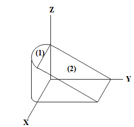
Mass of segment (1) will be
Similarly,
Mass of segment (2) will be

Step by step
Solved in 4 steps with 1 images

- Aluminum Bronze Steel 2P 3P P 4P - - 1.0 m 0.8 m FIG. P2.16 2.16 A compound bar consisting of bronze, aluminum, and steel segments is loaded axially as shown in the figure. Determine the maximum allowable value of P if the change in length of the bar is limited to 2 mm and the working stresses pre- scribed in the table are not to be exceeded. A (mm²) E (GPa) G, (MPa) Вronze 450 83 120 Aluminum 600 70 80 Steel 300 200 140TWO SOLID CYLINDRICAL RODS ARE JOINED AT B AND LOADED AS SHOWN. ROD AB IS MADE OF STEEL (E = 210 GPa) AND ROD BC OF BRASS (E = 108 GPa). DETERMINE (A) THE TOTAL DEFORMATION OF THE COMPOSITE ROD ABC, (B) THE DEFLECTION OF POINT B. 40 KN 400 mm 600 mm A B C 30 mm 50 KN 50 mmTwo solid cylindrical rods are joined at B and loaded as shown. Rod AB is made of steel E 200GPa and rod BC of brass E 105GPa. Determine (a) the total deformation of the composite rod ABC, (b) the deflection of point B. 250 mm 300 mm 30 kN -30 mm 40 kN -50 mm
- A rigid bar, AB, is pinned at point B. Two other bars, AC and AD, are connected to point A to provide support for AB. We are investigating the behavior of this system under a specific load. Key Details: Bar properties: Material: Steel with Young's modulus (Esteel) of 200 GPa and coefficient of thermal expansion (a) of 11.7 x 10^-6 /°C. Cross-sectional area: AC: 1960 mm² AD: 1250 mm² Length: AC: √2 meters (square root of 2 meters) AD: 1 meter Inclination angles: AC: θ₁ (theta 1) = 30° from horizontal AD: θ₂ (theta 2) = 20° from horizontal Load on bar AB: Idealized linearly increasing load with a maximum value of 30 kN/m at point B. Problem Objectives: Determine the internal forces (axial forces) acting within bars AC and AD due to the applied load on AB. Calculate the displacement of point A in both horizontal (dA,x) and vertical (dA,y) directions.If the bar is cooled by 10°C, what would be the: Determine the internal forces (axial forces) acting within bars AC and AD…Two polymer bars are connected to a rigid plate at B, as shown. Bar (1) has a cross-sectional area of 1.71 in and an elastic modulus of 2050 ksi. Bar (2) has a cross-sectional area of 1.019 in? and an elastic modulus of 3910 ksi. Assume L-20 in. Lyn47 in. Q-6 kips. P-3.6 kips, and R-13.2 kips. Determine the horizontal deflection of end Crelative to end A. (1) (2) Answer: UCIA - in.At a temperature of 60°F, a 0.04-in. gap exists between the ends of the two bars shown. Bar (1) is an aluminum alloy [E = 10,000 ksi; v = 0.32; a = 12.7 x 10⁻⁶/°F] bar with a width of 3 in. and a thickness of 0.75 in. Bar (2) is a stainless steel [E = 28,000 ksi; v = 0.12; a = 8.6 x 10⁻⁶/°F] bar with a width of 2 in. and a thickness of 0.75 in. The supports at A and C are rigid. Determine the lowest temperature at which the two bars contact each other. (1) 3 in. 32 in. 90.2°F O 69.9°F 139.2°F 103.5°F O 111.0°F B ↑ 2 in. ↓ 44 in. -0.04-in. gap
- Steel 1 m Aluminum T 0.75 m Determine the maximum permissible value of T subject to the following conditions: tt S 80 MPa, Tal 50 MPa, and the angle of rotation of the free end is limited to 0.1 radian. For T. Hollow Solid d= 30 mm D= 40 mm %3D steel, G = 82 GPa and for aluminum, G= 28 GPa. %3D d = 30 mm %3DA 5.2-m-long aluminum tube (1) is to be connected to a 2.2-m-long bronze pipe (2) at B. When put in place, however, a gap of 9 mm exists between the two members, as shown. Aluminum tube (1) has an elastic modulus of 69 GPa and a cross-sectional area of 1980 mm2. Bronze pipe (2) has an elastic modulus of 93 GPa and a cross-sectional area of 3970 mm2. If bolts are inserted in the flanges and tightened so that the gap at B is closed, determine: (a) the normal stresses ?1, ?2 produced in each of the members. (b) the displacement (change in length of material (2), up is positive) uB of flange B with respect to support A. 5.2 m 2.2 m Answers: (a) 0₁ = (b) Ug = C (1) B (2) -95.40 1.126 9 mm MPa, 0₂ = mm. -47.58 MPaAt a temperature of 60°F, a 0.04-in. gap exists between the ends of the two bars shown. Bar (1) is an aluminum alloy [E = 10,000 ksi; v = 0.32; a = 14.4 x 10⁻⁶/°F] bar with a width of 3 in. and a thickness of 0.75 in. Bar (2) is a stainless steel [E = 28,000 ksi; v = 0.12; a = 9.6 × 10⁻⁶/°F] bar with a width of 2 in. and a thickness of 0.75 in. The supports at A and Care rigid. Determine the lowest temperature at which the two bars contact each other. (1) 3 in. 32 in. 105.3°F 75.3°F O 147.3°F 86.6°F 113.4°F B ↑ 2 in. ↓ (2) 44 in. 0.04-in. gap
- At a temperature of 60°F, a 0.04-in. gap exists between the ends of the two bars shown. Bar (1) is an aluminum alloy [E = 10,000 ksi; v = 0.32; a = 13.4 x 10⁻⁶/°F] bar with a width of 3 in. and a thickness of 0.75 in. Bar (2) is a stainless steel [E = 28,000 ksi; v = 0.12; a = 10.1 x 10⁻⁶/°F] bar with a width of 2 in. and a thickness of 0.75 in. The supports at A and Care rigid. Determine the lowest temperature at which the two bars contact each other. (1) ↑ 3 in. 32 in. O 75.9°F O 146.5°F O 105.8°F O 122.3°F O 111.3°F 2 in. (2) 44 in. -0.04-in. gapA hollow aluminum tube is rigidly attached between steel rod and a bronze rod as shown. Axial loads are applied at the positions indicated. Find the maximum value of P that will not exceed a stress in aluminum of 80 MPa, in steel of 150 MPa or bronze of 100 MPa. Steel Aluminum Bronze А P> ЗР - 2P outside = 30 mm d inside = 20 mm d d = 16 mm d = 60 mm -100mm- -150mm- -125mm-An aluminum rod is rigidly attached between a steel rod and a bronze rod as shown in Fig. P-108. Axial loads are applied at the positions indicated. Find the maximum value of P that will not exceed a stress in steel of 140 MPa, in aluminum of 90 MPa, or in bronze of 100 MPa. Figure P-108 PARTNER Aluminum A=400 mm² Steel A = 500 mm² 2.5 m 2.0 m Bronze A = 200 mm² 1.5 m 2P