10. Of the values listed, the most realistic value for open-loop gain of an op-amp is (c) 80 dB (a) 1 (b) 2000 (d) 100,000 11. A certain op-amp has bias currents of 50 µA and 49.3 µA. The input offset current is (a) 700 nA (b) 99.3 µA (e) 49.7 µA (d) none of these 12. The output of a particular op-amp increases 8 V in 12 us. The slew rate is (a) 96 V/us (b) 0.67 V/us (c) 1.5 V/us (d) none of these
10. Of the values listed, the most realistic value for open-loop gain of an op-amp is (c) 80 dB (a) 1 (b) 2000 (d) 100,000 11. A certain op-amp has bias currents of 50 µA and 49.3 µA. The input offset current is (a) 700 nA (b) 99.3 µA (e) 49.7 µA (d) none of these 12. The output of a particular op-amp increases 8 V in 12 us. The slew rate is (a) 96 V/us (b) 0.67 V/us (c) 1.5 V/us (d) none of these

Power System Analysis and Design (MindTap Course List)
6th Edition
ISBN:9781305632134
Author:J. Duncan Glover, Thomas Overbye, Mulukutla S. Sarma
Publisher:J. Duncan Glover, Thomas Overbye, Mulukutla S. Sarma
Chapter12: Power System Controls
Section: Chapter Questions
Problem 12.3P

Related questions
Question
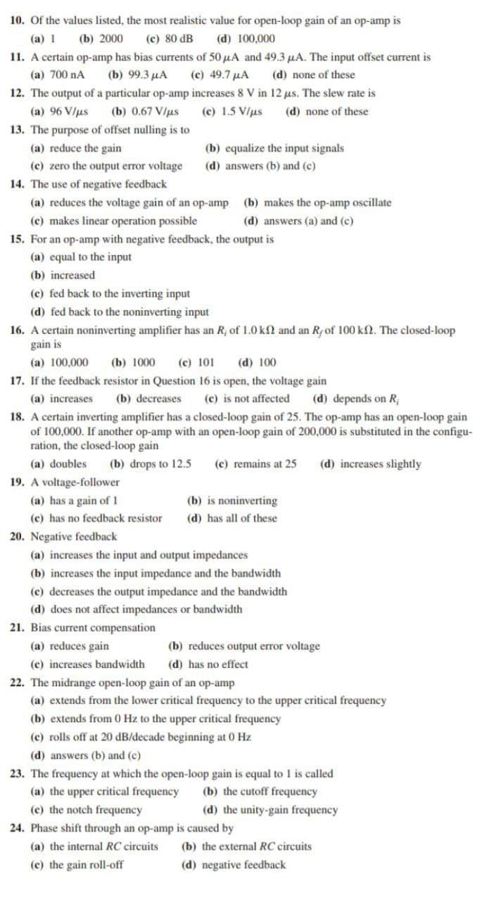
Transcribed Image Text:10. Of the values listed, the most realistic value for open-loop gain of an op-amp is
(a) 1
(b) 2000
(c) 80 dB
(d) 100,000
11. A certain op-amp has bias currents of 50 µA and 49.3 uA. The input offset current is
(c) 49.7 µA
12. The output of a particular op-amp increases 8 V in 12 us. The slew rate is
(a) 700 nA
(b) 99.3 µA
(d) none of these
(a) 96 V/us
(b) 0.67 V/us
(c) 1.5 V/us
(d) none of these
13. The purpose of offset nulling is to
(a) reduce the gain
(b) equalize the input signals
(c) zero the output error voltage
(d) answers (b) and (c)
14. The use of negative feedback
(a) reduces the voltage gain of an op-amp
(c) makes linear operation possible
15. For an op-amp with negative feedback, the output is
(b) makes the op-amp oscillate
(d) answers (a) and (c)
(a) equal to the input
(b) increased
(c) fed back to the inverting input
(d) fed back to the noninverting input
16. A certain noninverting amplifier has an R; of 1.0 kN and an Rfof 100 k2. The closed-loop
gain is
(c) 101
17. If the feedback resistor in Question 16 is open, the voltage gain
(a) 100,000
(b) 1000
(d) 100
(a) increases
(b) decreases
(c) is not affected
(d) depends on R;
18. A certain inverting amplifier has a closed-loop gain of 25. The op-amp has an open-loop gain
of 100,000. If another op-amp with an open-loop gain of 200,000 is substituted in the configu-
ration, the closed-loop gain
(a) doubles
(b) drops to 12.5
(c) remains at 25
(d) increases slightly
19. A voltage-follower
(a) has a gain of 1
(b) is noninverting
(c) has no feedback resistor
(d) has all of these
20. Negative feedback
(a) increases the input and output impedances
(b) increases the input impedance and the bandwidth
(c) decreases the output impedance and the bandwidth
(d) does not affect impedances or bandwidth
21. Bias current compensation
(a) reduces gain
(b) reduces output error voltage
(c) increases bandwidth
(d) has no effect
22. The midrange open-loop gain of an op-amp
(a) extends from the lower critical frequency to the upper critical frequency
(b) extends from 0 Hz to the upper critical frequency
(c) rolls off at 20 dB/decade beginning at 0 Hz
(d) answers (b) and (c)
23. The frequency at which the open-loop gain is equal to 1 is called
(b) the cutoff frequency
(a) the upper critical frequency
(c) the notch frequency
(d) the unity-gain frequency
24. Phase shift through an op-amp is caused by
(a) the internal RC circuits
(b) the external RC circuits
(c) the gain roll-off
(d) negative feedback
Expert Solution
This question has been solved!
Explore an expertly crafted, step-by-step solution for a thorough understanding of key concepts.

Step by step
Solved in 2 steps with 1 images

Knowledge Booster


Learn more about
Need a deep-dive on the concept behind this application? Look no further. Learn more about this topic, electrical-engineering and related others by exploring similar questions and additional content below.Recommended textbooks for you
Power System Analysis and Design (MindTap Course …
Electrical Engineering
ISBN:
9781305632134
Author:
J. Duncan Glover, Thomas Overbye, Mulukutla S. Sarma
Publisher:
Cengage Learning
Power System Analysis and Design (MindTap Course …
Electrical Engineering
ISBN:
9781305632134
Author:
J. Duncan Glover, Thomas Overbye, Mulukutla S. Sarma
Publisher:
Cengage Learning