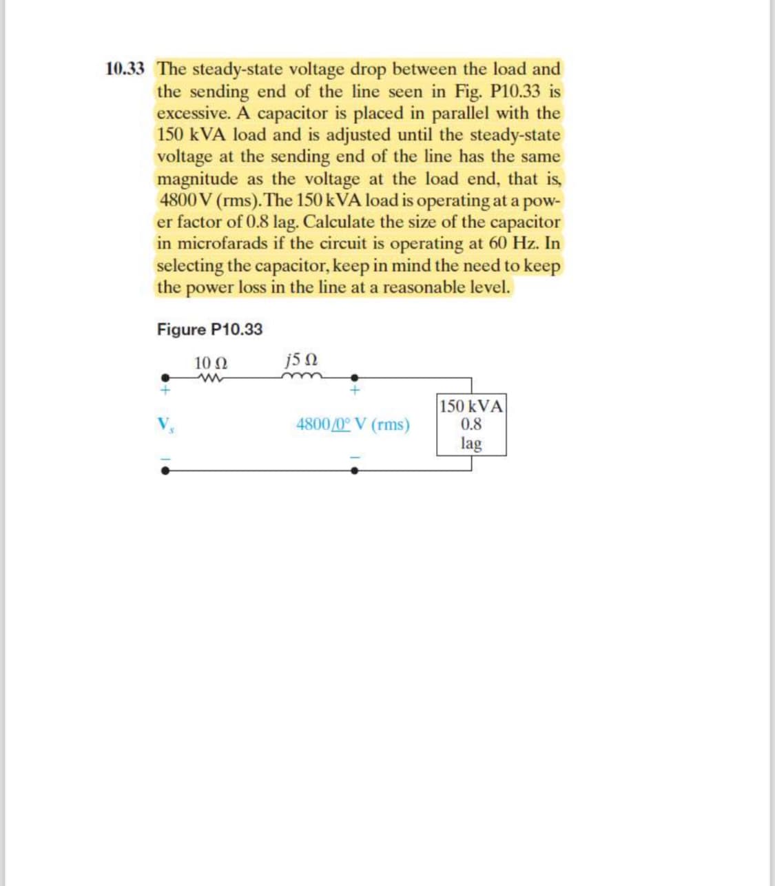
10.33 The steady-state voltage drop between the load and the sending end of the line seen in Fig. P10.33 is excessive. A capacitor is placed in parallel with the 150 kVA load and is adjusted until the steady-state voltage at the sending end of the line has the same magnitude as the voltage at the load end, that is, 4800 V (rms). The 150 kVA load is operating at a pow- er factor of 0.8 lag. Calculate the size of the capacitor in microfarads if the circuit is operating at 60 Hz. In selecting the capacitor, keep in mind the need to keep the power loss in the line at a reasonable level. Figure P10.33 V 10 Q2 j5 Q 4800/0° V (rms) 150 kVA 0.8 lag
10.33 The steady-state voltage drop between the load and the sending end of the line seen in Fig. P10.33 is excessive. A capacitor is placed in parallel with the 150 kVA load and is adjusted until the steady-state voltage at the sending end of the line has the same magnitude as the voltage at the load end, that is, 4800 V (rms). The 150 kVA load is operating at a pow- er factor of 0.8 lag. Calculate the size of the capacitor in microfarads if the circuit is operating at 60 Hz. In selecting the capacitor, keep in mind the need to keep the power loss in the line at a reasonable level. Figure P10.33 V 10 Q2 j5 Q 4800/0° V (rms) 150 kVA 0.8 lag

Introductory Circuit Analysis (13th Edition)
13th Edition
ISBN:9780133923605
Author:Robert L. Boylestad
Publisher:Robert L. Boylestad
Chapter1: Introduction
Section: Chapter Questions
Problem 1P: Visit your local library (at school or home) and describe the extent to which it provides literature...

Related questions
Question
Please show all steps
Transcribed Image Text:10.33 The steady-state voltage drop between the load and
the sending end of the line seen in Fig. P10.33 is
excessive. A capacitor is placed in parallel with the
150 kVA load and is adjusted until the steady-state
voltage at the sending end of the line has the same
magnitude as the voltage at the load end, that is,
4800 V (rms). The 150 kVA load is operating at a pow-
er factor of 0.8 lag. Calculate the size of the capacitor
in microfarads if the circuit is operating at 60 Hz. In
selecting the capacitor, keep in mind the need to keep
the power loss in the line at a reasonable level.
Figure P10.33
10 Ω
j5 Ω
4800/0° V (rms)
150 kVA
0.8
lag
Expert Solution
This question has been solved!
Explore an expertly crafted, step-by-step solution for a thorough understanding of key concepts.

Step by step
Solved in 3 steps with 2 images

Knowledge Booster


Learn more about
Need a deep-dive on the concept behind this application? Look no further. Learn more about this topic, electrical-engineering and related others by exploring similar questions and additional content below.Recommended textbooks for you
Introductory Circuit Analysis (13th Edition)
Electrical Engineering
ISBN:
9780133923605
Author:
Robert L. Boylestad
Publisher:
PEARSON

Delmar's Standard Textbook Of Electricity
Electrical Engineering
ISBN:
9781337900348
Author:
Stephen L. Herman
Publisher:
Cengage Learning

Programmable Logic Controllers
Electrical Engineering
ISBN:
9780073373843
Author:
Frank D. Petruzella
Publisher:
McGraw-Hill Education
Introductory Circuit Analysis (13th Edition)
Electrical Engineering
ISBN:
9780133923605
Author:
Robert L. Boylestad
Publisher:
PEARSON
Delmar's Standard Textbook Of Electricity
Electrical Engineering
ISBN:
9781337900348
Author:
Stephen L. Herman
Publisher:
Cengage Learning
Programmable Logic Controllers
Electrical Engineering
ISBN:
9780073373843
Author:
Frank D. Petruzella
Publisher:
McGraw-Hill Education

Fundamentals of Electric Circuits
Electrical Engineering
ISBN:
9780078028229
Author:
Charles K Alexander, Matthew Sadiku
Publisher:
McGraw-Hill Education

Electric Circuits. (11th Edition)
Electrical Engineering
ISBN:
9780134746968
Author:
James W. Nilsson, Susan Riedel
Publisher:
PEARSON

Engineering Electromagnetics
Electrical Engineering
ISBN:
9780078028151
Author:
Hayt, William H. (william Hart), Jr, BUCK, John A.
Publisher:
Mcgraw-hill Education,