
Structural Analysis
6th Edition
ISBN: 9781337630931
Author: KASSIMALI, Aslam.
Publisher: Cengage,
expand_more
expand_more
format_list_bulleted
Concept explainers
Question
Draw shear force and bending moment diagrams for the given simply supported beam.

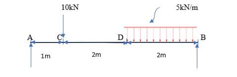
Transcribed Image Text:10kN
5kN/m
1m
2m
2m
Expert Solution

arrow_forward

Step 1
Draw a free body diagram converting the UDL into a point load
As UDL is given 5kn and it is acting on the 2m length
Therefore, load will be 5 x 2 = 10 kN acting on center of 1m from point B.
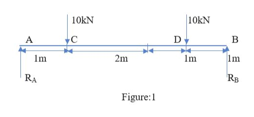
arrow_forward
Step 2
Take moments @A, we know the condition
Anticlockwise moment = clockwise moments
We know moment = force x perpendicular distance
RB x 5 = (10 x 1) + (10 x 4)
RB x 5 = 50
RB = 50/5= 10 kN.
Summation of upward force = summation of downward force
RA + RB = 10+10
RA + 10 = 20
RA = 20 – 10
RA = 10 kN
Trending nowThis is a popular solution!
Step by stepSolved in 4 steps with 3 images

Knowledge Booster
Learn more about
Need a deep-dive on the concept behind this application? Look no further. Learn more about this topic, civil-engineering and related others by exploring similar questions and additional content below.Similar questions
- From the following description of the load path, where and in what direction do you think the external load is applied? The upper horizontal acts as a beam carrying shear and bending to the ends where the load is carried in bending, torsion and shear by the verticals. The verticals act like cantilevers held in place by the support feet Vertical- Support feet-> Upper horizontal Lower horizontal Select one: O a Vertically upwards on the upper horizontal Ob Vertically down on the upper horizontal O Vertically down on the lower horizontal Od Horizontally perpendicular to the upper horizontalarrow_forwardGiven the following, please solve this problem step by step so I can understand. PLEASE SHOW ALL WORK IN NEAT HAND WRITINGarrow_forwardUse the graphical method to construct the shear-force and bending-moment diagrams for the beam shown. Let a = 3.2 ft, b = 9.6 ft, c = 3.6 ft, MA = 6700 lb·ft, P = 3000 lb, and w = 660 lb/ft. Label all significant points on each diagram and identify the maximum moments (both positive and negative) along with their respective locations. Clearly differentiate straight-line and curved portions of the diagrams. Determine the maximum shear force and bending moment in the beam.Note that answers may be positive or negative. Here, "maximum" refers to the largest magnitude value, but you should enter your shear force and bending moment with the correct sign, using the sign convention presented in Section 7.2 of the textbook. If the magnitudes of the largest positive and largest negative values are the same, enter a positive number.arrow_forward
arrow_back_ios
arrow_forward_ios
Recommended textbooks for you
- Structural Analysis (10th Edition)Civil EngineeringISBN:9780134610672Author:Russell C. HibbelerPublisher:PEARSONPrinciples of Foundation Engineering (MindTap Cou...Civil EngineeringISBN:9781337705028Author:Braja M. Das, Nagaratnam SivakuganPublisher:Cengage Learning
- Fundamentals of Structural AnalysisCivil EngineeringISBN:9780073398006Author:Kenneth M. Leet Emeritus, Chia-Ming Uang, Joel LanningPublisher:McGraw-Hill EducationTraffic and Highway EngineeringCivil EngineeringISBN:9781305156241Author:Garber, Nicholas J.Publisher:Cengage Learning


Structural Analysis (10th Edition)
Civil Engineering
ISBN:9780134610672
Author:Russell C. Hibbeler
Publisher:PEARSON

Principles of Foundation Engineering (MindTap Cou...
Civil Engineering
ISBN:9781337705028
Author:Braja M. Das, Nagaratnam Sivakugan
Publisher:Cengage Learning

Fundamentals of Structural Analysis
Civil Engineering
ISBN:9780073398006
Author:Kenneth M. Leet Emeritus, Chia-Ming Uang, Joel Lanning
Publisher:McGraw-Hill Education


Traffic and Highway Engineering
Civil Engineering
ISBN:9781305156241
Author:Garber, Nicholas J.
Publisher:Cengage Learning