11-23 Determine the force transmitted by member CD of the truss shown in Fig. P11-23. 300 Ib 400 Ib 12 ft 10 ft - 10 ft 10 ft 10 ft 500 Ib Fig. P11-23
11-23 Determine the force transmitted by member CD of the truss shown in Fig. P11-23. 300 Ib 400 Ib 12 ft 10 ft - 10 ft 10 ft 10 ft 500 Ib Fig. P11-23

International Edition---engineering Mechanics: Statics, 4th Edition
4th Edition
ISBN:9781305501607
Author:Andrew Pytel And Jaan Kiusalaas
Publisher:Andrew Pytel And Jaan Kiusalaas
Chapter10: Virtual Work And Potential Energy
Section: Chapter Questions
Problem 10.55P: Solve Prob. 10.54 assuming that A and B are connected by a spring of stiffness k = 0.3 W/b and free...

Related questions
Question
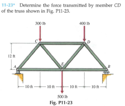
Transcribed Image Text:11-23 Determine the force transmitted by member CD
of the truss shown in Fig. P11-23.
300 Ib
400 Ib
12 ft
10 ft
- 10 ft
10 ft
10 ft
500 Ib
Fig. P11-23
Expert Solution
This question has been solved!
Explore an expertly crafted, step-by-step solution for a thorough understanding of key concepts.

This is a popular solution!

Trending now
This is a popular solution!

Step by step
Solved in 3 steps with 4 images

Recommended textbooks for you
International Edition---engineering Mechanics: St…
Mechanical Engineering
ISBN:
9781305501607
Author:
Andrew Pytel And Jaan Kiusalaas
Publisher:
CENGAGE L
International Edition---engineering Mechanics: St…
Mechanical Engineering
ISBN:
9781305501607
Author:
Andrew Pytel And Jaan Kiusalaas
Publisher:
CENGAGE L