11. In the circuit shown in Figure 9-34, assume that R, has a resistance of 4 $2 and R2 has a resistance of 20 2. Battery Es has a voltage of 48 V. What is the Thevenin equivalent voltage for this circuit across Terminals A and B? ETHEV = 12. What is the equivalent Thevenin resistance for the circuit described in Question 11? RTHEV = , Ω %3D
11. In the circuit shown in Figure 9-34, assume that R, has a resistance of 4 $2 and R2 has a resistance of 20 2. Battery Es has a voltage of 48 V. What is the Thevenin equivalent voltage for this circuit across Terminals A and B? ETHEV = 12. What is the equivalent Thevenin resistance for the circuit described in Question 11? RTHEV = , Ω %3D

Chapter9: Lighting Branch Circuit For The Master Bedroom
Section: Chapter Questions
Problem 20R: Show your calculations of how to select a proper wall box for the clothes closet luminaire switch....

Related questions

Question
Transcribed Image Text:SECTION 2 Basic Electric Circuits
R1
Es
R2
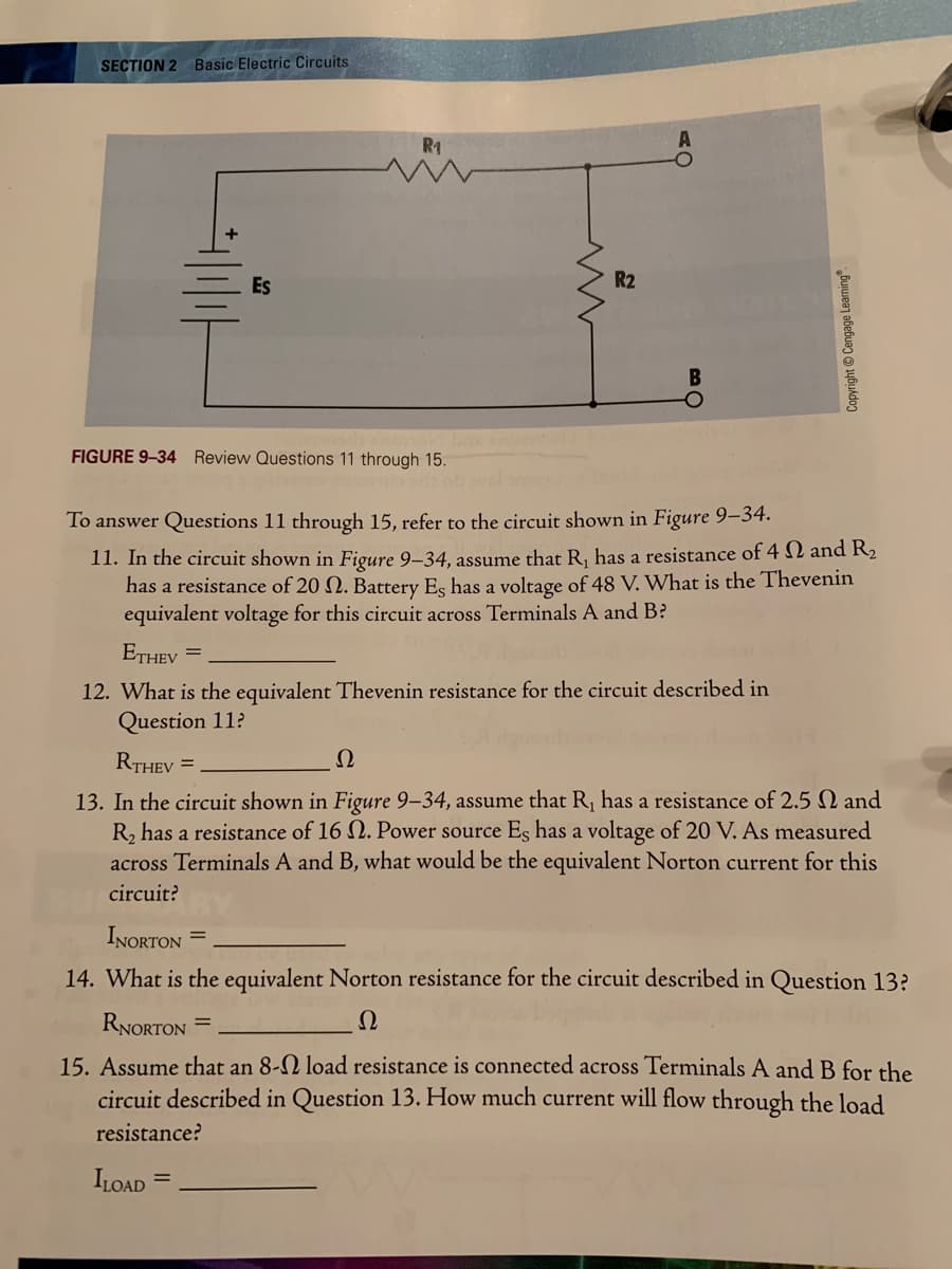
FIGURE 9-34 Review Questions 11 through 15.
To answer Questions 11 through 15, refer to the circuit shown in Figure 9–34.
11. In the circuit shown in Figure 9–34, assume that R, has a resistance of 4 N and R2
has a resistance of 20 N. Battery Es has a voltage of 48 V. What is the Thevenin
equivalent voltage for this circuit across Terminals A and B?
ETHEV
%3D
12. What is the equivalent Thevenin resistance for the circuit described in
Question 11?
RTHEV =
Ω
13. In the circuit shown in Figure 9-34, assume that R, has a resistance of 2.5 N and
R, has a resistance of 16 N. Power source Es has a voltage of 20 V. As measured
across Terminals A and B, what would be the equivalent Norton current for this
circuit?
INORTON =
14. What is the equivalent Norton resistance for the circuit described in Question 13?
RNORTON =
Ω
15. Assume that an 8-N load resistance is connected across Terminals A and B for the
circuit described in Question 13. How much current will flow through the load
resistance?
ILOAD
Copyright © Cengage Learning.
Expert Solution
This question has been solved!
Explore an expertly crafted, step-by-step solution for a thorough understanding of key concepts.

This is a popular solution!

Trending now
This is a popular solution!

Step by step
Solved in 2 steps

Knowledge Booster


Learn more about
Need a deep-dive on the concept behind this application? Look no further. Learn more about this topic, electrical-engineering and related others by exploring similar questions and additional content below.Recommended textbooks for you
EBK ELECTRICAL WIRING RESIDENTIAL
Electrical Engineering
ISBN:
9781337516549
Author:
Simmons
Publisher:
CENGAGE LEARNING - CONSIGNMENT
EBK ELECTRICAL WIRING RESIDENTIAL
Electrical Engineering
ISBN:
9781337516549
Author:
Simmons
Publisher:
CENGAGE LEARNING - CONSIGNMENT