111. For the truss shown in Fig. P-111, calculate the stresses in members CE area of each member is 1.8 in.2. Indicate tensi DF. The cross-sectional compression (C). ce = 9260 psi (T); ode = 22.2 ksi (T); df = 18 A 8 ft B Ans. 6 ft 8 ft D 6 ft 8 ft E 30 kips F #
111. For the truss shown in Fig. P-111, calculate the stresses in members CE area of each member is 1.8 in.2. Indicate tensi DF. The cross-sectional compression (C). ce = 9260 psi (T); ode = 22.2 ksi (T); df = 18 A 8 ft B Ans. 6 ft 8 ft D 6 ft 8 ft E 30 kips F #

Chapter4: Plane And Space Trusses
Section: Chapter Questions
Problem 32P

Related questions
Question
answer the following problems using method of joints and method of section separately in solving for the unknown forces and indicate if the forces/stresses are in tension or compression. Provide each solutions with a proper discussion and illustration.
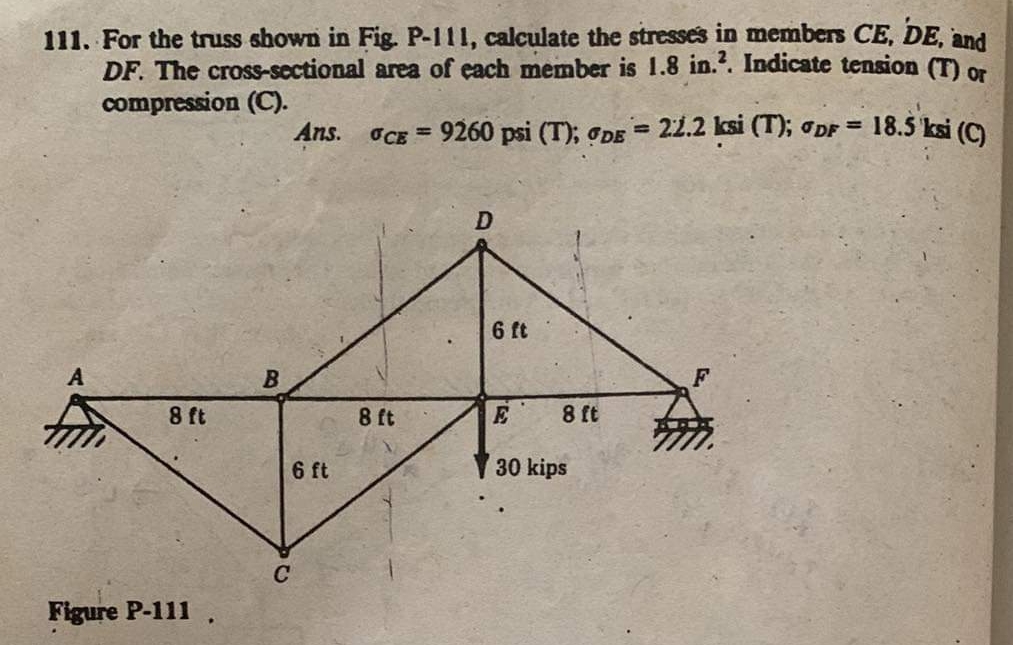
Transcribed Image Text:111. For the truss shown in Fig. P-111, calculate the stresses in members CE, DE, and
DF. The cross-sectional area of each member is 1.8 in.2. Indicate tension (T) or
compression (C).
OCE = 9260 psi (T); DE = 22.2 ksi (T); DF = 18.5 ksi (C)
8 ft
Figure P-111
B
Ans.
6 ft
C
8 ft
D
6 ft
8 ft
E
30 kips
Expert Solution
This question has been solved!
Explore an expertly crafted, step-by-step solution for a thorough understanding of key concepts.

Step by step
Solved in 2 steps with 1 images

Knowledge Booster


Learn more about
Need a deep-dive on the concept behind this application? Look no further. Learn more about this topic, civil-engineering and related others by exploring similar questions and additional content below.Recommended textbooks for you