16-foot-long

Chapter2: Loads On Structures
Section: Chapter Questions
Problem 1P

Related questions
Question
100%
A 16-foot-long single overhang beam is loaded as shown. Assuming a W8 x 35 determine the maximum bending stress developed. The informally distributed load of 3 k/ft include the weight of the beam. Given: A992 steel Fb = 30 ksi.
For W8 x 35 section properties see Table A3 (Textbook Appendix) (Provided)
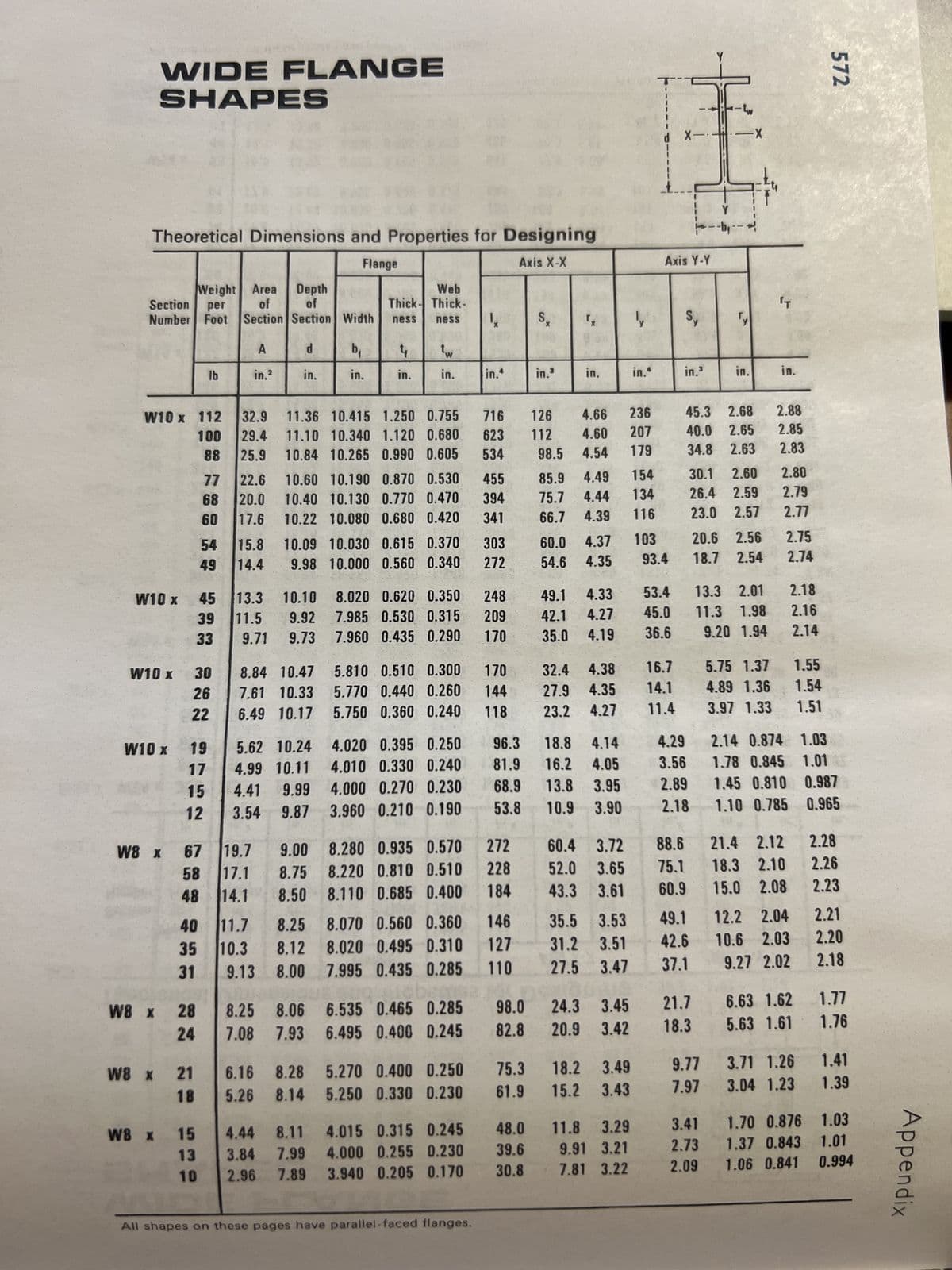
Transcribed Image Text:WIDE FLANGE
SHAPES
Theoretical Dimensions and Properties for Designing
Flange
Axis X-X
Weight Area Depth
Section
per
of of
Number Foot Section Section
W10 x 112
100
88
W10 x
W10 x
W10 x
W8 x
30
26
22
19
17
15
12
58
48
45
39
33
67
40
35
31
W8 x 28
24
lb
77
68
60
W8 x 21
18
54
49
W8 x 15
13
10
A
in.²
32.9
29.4
25.9
22.6
20.0
17.6
15.8
14.4
13.3
11.5
9.71
d
in.
19.7
17.1
14.1
10.10
9.92
9.73
8.84 10.47
7.61 10.33
6.49 10.17
5.62 10.24
4.99 10.11
4.41 9.99
3.54 9.87
Web
Thick- Thick-
Width ness ness
11.36 10.415 1.250 0.755
716
11.10 10.340 1.120 0.680 623
10.84 10.265 0.990 0.605
534
10.09 10.030 0.615 0.370
9.98 10.000 0.560 0.340
9.00
8.75
8.50
b₁
in.
10.60 10.190 0.870 0.530 455
10.40 10.130 0.770 0.470 394
10.22 10.080 0.680 0.420 341
4
in.
8.25 8.06
7.08 7.93
in.
6.16 8.28
5.26 8.14
8.020 0.620 0.350
7.985 0.530 0.315
7.960 0.435 0.290
Į
in.^
5.810 0.510 0.300 170
5.770 0.440 0.260 144
5.750 0.360 0.240 118
6.535 0.465 0.285
6.495 0.400 0.245
5.270 0.400 0.250
5.250 0.330 0.230
303
272
8.280 0.935 0.570 272
8.220 0.810 0.510 228
184
8.110 0.685 0.400
4.44 8.11 4.015 0.315 0.245
3.84 7.99 4.000 0.255 0.230
2.96
7.89 3.940 0.205 0.170
248
209
170
All shapes on these pages have parallel-faced flanges.
146
127
110
96.3
18.8 4.14
4.020 0.395 0.250
4.010 0.330 0.240 81.9
16.2
4.05
68.9
13.8
3.95
4.000 0.270 0.230
3.960 0.210 0.190
53.8 10.9
3.90
98.0
82.8
S₂
75.3
61.9
in.3
48.0
39.6
30.8
"x
in.
60.0 4.37
54.6 4.35
126 4.66 236
112 4.60
98.5 4.54
207
179
85.9 4.49 154
75.7 4.44 134
66.7 4.39 116
49.1 4.33
42.1
4.27
35.0 4.19
32.4 4.38
27.9 4.35
23.2
4.27
60.4 3.72
52.0 3.65
43.3 3.61
24.3
20.9
11.7
35.5 3.53
8.25 8.070 0.560 0.360
31.2 3.51
8.12 8.020 0.495 0.310
10.3
9.13 8.00 7.995 0.435 0.285
27.5 3.47
3.45
3.42
18.2 3.49
15.2 3.43
in."
11.8 3.29
9.91 3.21
7.81 3.22
d X-
ly Sy
Axis Y-Y
103
93.4
53.4
45.0
36.6
16.7
14.1
11.4
in.3
4.29
3.56
2.89
2.18
88.6
75.1
60.9
49.1
42.6
37.1
45.3 2.68
40.0 2.65
34.8 2.63
Y
21.7
18.3
-X
E
30.1 2.60
26.4 2.59
23.0 2.57
9.77
7.97
20.6 2.56
18.7 2.54
13.3 2.01
11.3 1.98
9.20 1.94
'T
in.
2.88
2.85
2.83
2.80
2.79
2.77
2.75
2.74
2.18
2.16
2.14
5.75 1.37 1.55
4.89
4.89 1.36
1.36
1.54
3.97 1.33
1.51
572
2.14 0.874 1.03
1.78 0.845 1.01
1.45 0.810 0.987
1.10 0.785 0.965
21.4 2.12
2.28
18.3 2.10 2.26
15.0 2.08 2.23
12.2 2.04
10.6 2.03
9.27 2.02
2.21
2.20
2.18
6.63 1.62
1.77
5.63 1.61 1.76
3.71 1.26 1.41
3.04 1.23 1.39
3.41 1.70 0.876 1.03
2.73 1.37 0.843 1.01
1.06 0.841 0.994
2.09
Appendix
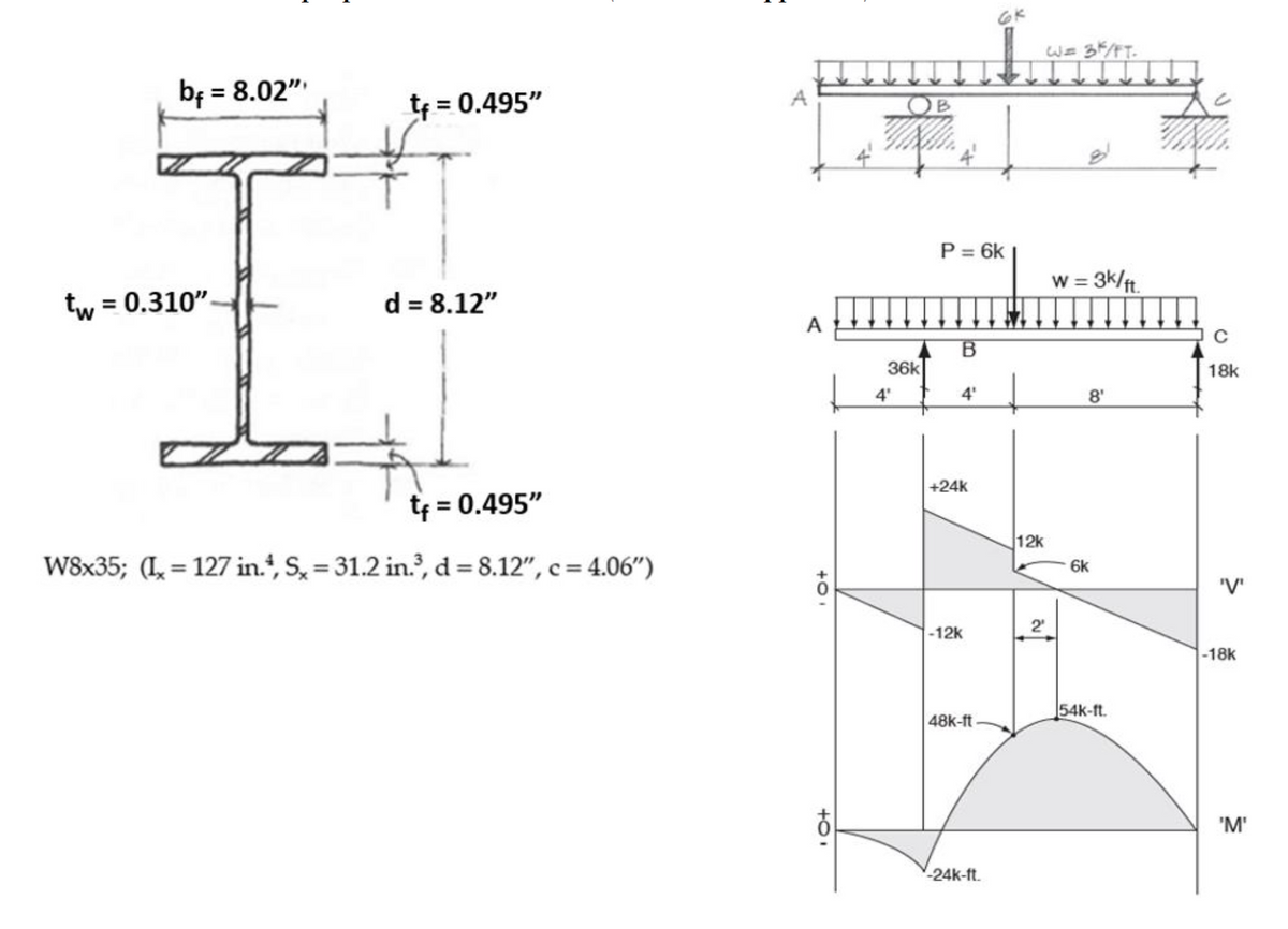
Transcribed Image Text:b₁ = 8.02"
tw = 0.310".
t₁ = 0.495"
d = 8.12"
t₁ = 0.495"
W8x35; (I=127 in., S, = 31.2 in.³, d = 8.12", c=4.06")
A
A
+0
+0.
OB
36k
4'
&
P = 6k
B
4'
+24k
-12k
48k-ft
-24k-ft.
12k
2
W = 3K/FT.
w = 3k/ft.
8'
6k
54k-ft.
с
18k
'V'
-18k
'M'
Expert Solution
This question has been solved!
Explore an expertly crafted, step-by-step solution for a thorough understanding of key concepts.

This is a popular solution!

Trending now
This is a popular solution!

Step by step
Solved in 2 steps with 2 images

Knowledge Booster


Learn more about
Need a deep-dive on the concept behind this application? Look no further. Learn more about this topic, civil-engineering and related others by exploring similar questions and additional content below.Recommended textbooks for you

Structural Analysis (10th Edition)
Civil Engineering
ISBN:
9780134610672
Author:
Russell C. Hibbeler
Publisher:
PEARSON

Principles of Foundation Engineering (MindTap Cou…
Civil Engineering
ISBN:
9781337705028
Author:
Braja M. Das, Nagaratnam Sivakugan
Publisher:
Cengage Learning
Structural Analysis (10th Edition)
Civil Engineering
ISBN:
9780134610672
Author:
Russell C. Hibbeler
Publisher:
PEARSON
Principles of Foundation Engineering (MindTap Cou…
Civil Engineering
ISBN:
9781337705028
Author:
Braja M. Das, Nagaratnam Sivakugan
Publisher:
Cengage Learning

Fundamentals of Structural Analysis
Civil Engineering
ISBN:
9780073398006
Author:
Kenneth M. Leet Emeritus, Chia-Ming Uang, Joel Lanning
Publisher:
McGraw-Hill Education


Traffic and Highway Engineering
Civil Engineering
ISBN:
9781305156241
Author:
Garber, Nicholas J.
Publisher:
Cengage Learning