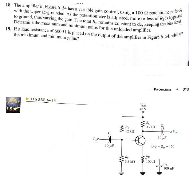
18. The amplifier in Figure 6-54 has a variable gain control, using a 100 2 potentiometer for Re with the wiper ac-grounded. As the potentiometer is adjusted, more or less of RE is bypassed to ground, thus varying the gain. The total Rg remains constant to dc, keeping the bias fixed. Determine the maximum and minimum gains for this unloaded amplifier. 19. If a load resistance of 600 is placed
18. The amplifier in Figure 6-54 has a variable gain control, using a 100 2 potentiometer for Re with the wiper ac-grounded. As the potentiometer is adjusted, more or less of RE is bypassed to ground, thus varying the gain. The total Rg remains constant to dc, keeping the bias fixed. Determine the maximum and minimum gains for this unloaded amplifier. 19. If a load resistance of 600 is placed

Introductory Circuit Analysis (13th Edition)
13th Edition
ISBN:9780133923605
Author:Robert L. Boylestad
Publisher:Robert L. Boylestad
Chapter1: Introduction
Section: Chapter Questions
Problem 1P: Visit your local library (at school or home) and describe the extent to which it provides literature...

Related questions
Question
100%
18
Transcribed Image Text:18. The amplifier in Figure 6-54 has a variable gain control, using a 100 2 potentiometer for Re
with the wiper ac-grounded. As the potentiometer is adjusted, more or less of RE is bypassed
to ground, thus varying the gain. The total Rg remains constant to dc, keeping the bias fixed.
Determine the maximum and minimum gains for this unloaded amplifier.
19. If a load resistance of 600 2 is placed on the output of the amplifier in Figure 6-54, what are
the maximum and minimum gains?
Muk Sim
2012 2009
T Spice
FIGURE 6-54
G
10 μF
www
+1₁
R₁
12 ΚΩ
R₂
3.3 ΚΩ
Vcc
+8 V
1₁
Re
330 Ω
RE
PROBLEMS + 313
HE
10 μF
Boc=B=150
100 Ω
C₂
100 μF
AME
Expert Solution
This question has been solved!
Explore an expertly crafted, step-by-step solution for a thorough understanding of key concepts.

This is a popular solution!

Trending now
This is a popular solution!

Step by step
Solved in 4 steps with 27 images

Recommended textbooks for you
Introductory Circuit Analysis (13th Edition)
Electrical Engineering
ISBN:
9780133923605
Author:
Robert L. Boylestad
Publisher:
PEARSON

Delmar's Standard Textbook Of Electricity
Electrical Engineering
ISBN:
9781337900348
Author:
Stephen L. Herman
Publisher:
Cengage Learning

Programmable Logic Controllers
Electrical Engineering
ISBN:
9780073373843
Author:
Frank D. Petruzella
Publisher:
McGraw-Hill Education
Introductory Circuit Analysis (13th Edition)
Electrical Engineering
ISBN:
9780133923605
Author:
Robert L. Boylestad
Publisher:
PEARSON
Delmar's Standard Textbook Of Electricity
Electrical Engineering
ISBN:
9781337900348
Author:
Stephen L. Herman
Publisher:
Cengage Learning
Programmable Logic Controllers
Electrical Engineering
ISBN:
9780073373843
Author:
Frank D. Petruzella
Publisher:
McGraw-Hill Education

Fundamentals of Electric Circuits
Electrical Engineering
ISBN:
9780078028229
Author:
Charles K Alexander, Matthew Sadiku
Publisher:
McGraw-Hill Education

Electric Circuits. (11th Edition)
Electrical Engineering
ISBN:
9780134746968
Author:
James W. Nilsson, Susan Riedel
Publisher:
PEARSON

Engineering Electromagnetics
Electrical Engineering
ISBN:
9780078028151
Author:
Hayt, William H. (william Hart), Jr, BUCK, John A.
Publisher:
Mcgraw-hill Education,