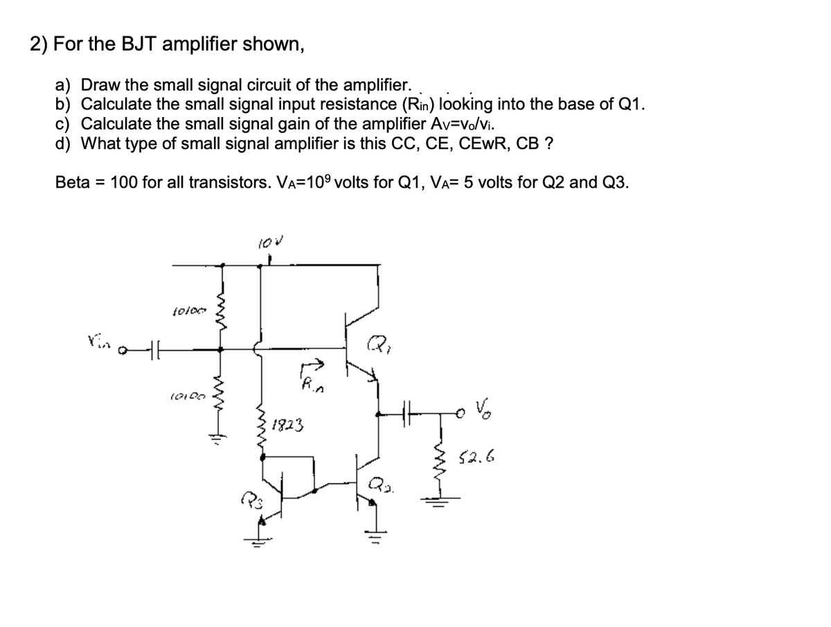
2) For the BJT amplifier shown, a) Draw the small signal circuit of the amplifier. b) Calculate the small signal input resistance (Rin) looking into the base of Q1. c) Calculate the small signal gain of the amplifier Av=vo/vi. d) What type of small signal amplifier is this CC, CE, CEWR, CB ? Beta = 100 for all transistors. VA=109 volts for Q1, VA= 5 volts for Q2 and Q3.


Please help with this BJT problem.
"According to company policy we need to answer the first four subparts of a question, if you want more to get solved you should post them to a different question."
Given a BJT amplifier circuit.
We need to draw a.c equivalent circuit.
We need to calculate the small signal input resistance Rin looking into base of transistor Q1.
We also need to calculate the voltage gain of the amplifier.
Given:
VA=109 for Q1
VA=5 for Q1
To determine the a.c resistance and output resistance by dc analysis:
D.C analysis:
Capacitors acts as open circuit and a.c voltages are deactivated.
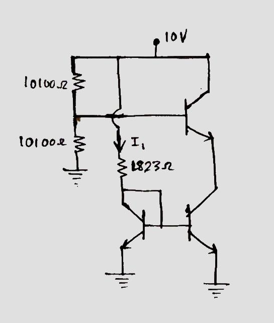
Applying KVL:
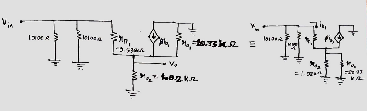
Thus, Output ac resistance across base of transistor Q1 is 0.536 kilo-ohm
Output resistance due to early voltage of transistor Q1 is 20.33 kilo-ohm.
Output resistance due to early voltage of transistor Q2 is 1.02 kilo-ohm.
a) To draw the a.c equivalent of the circuit:
The a.c equivalent circuit is:
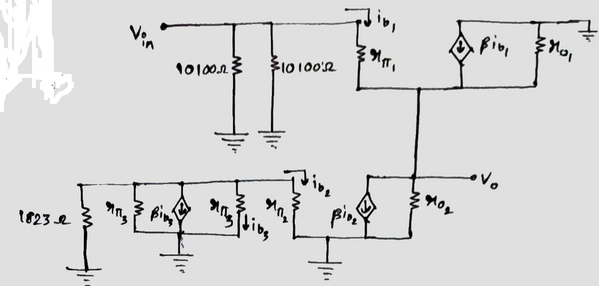
Clearly from the a.c equivalent circuit the no input voltage across the base in transistor Q2 & Q3 so .
So now the equivalent circuit is:

Step by step
Solved in 5 steps with 3 images


