2) The column is subjected to 3 forces as shown below. Determine the normal stress developed at each corner (A, B, C) of the section by following these steps. 2.1) determine centroid of this section (Y) 2.2) determine the moments of inertia about Y and Z axes 2.3) determine resultant axial force and its compressive stress 2.4) determine the bending moments about Y and Z axes due to each force 2.5) determine normal stress at point A, B and C 100N 3 ст Y+ 9 cm 6 cm Z+ 25N 50N 3 сm
2) The column is subjected to 3 forces as shown below. Determine the normal stress developed at each corner (A, B, C) of the section by following these steps. 2.1) determine centroid of this section (Y) 2.2) determine the moments of inertia about Y and Z axes 2.3) determine resultant axial force and its compressive stress 2.4) determine the bending moments about Y and Z axes due to each force 2.5) determine normal stress at point A, B and C 100N 3 ст Y+ 9 cm 6 cm Z+ 25N 50N 3 сm

Chapter2: Loads On Structures
Section: Chapter Questions
Problem 1P

Related questions
Question
100%
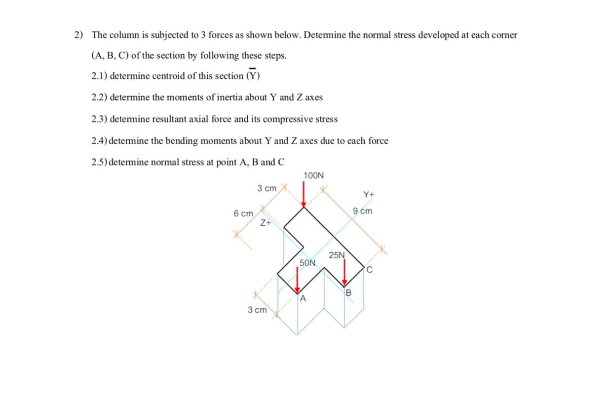
Thecolumnissubjectedto3forcesasshownbelow.Determinethenormalstressdevelopedateachcorner (A, B, C) of the section by following these steps.
2.1) determine centroid of this section (Y)
2.2) determine the moments of inertia about Y and Z axes
2.3) determine resultant axial force and its compressive stress
2.4) determine the bending moments about Y and Z axes due to each force 2.5) determine normal stress at point A, B and C
Transcribed Image Text:2) The column is subjected to 3 forces as shown below. Determine the normal stress developed at each corner
(A, B, C) of the section by following these steps.
2.1) determine centroid of this section (Y)
2.2) determine the moments of inertia about Y and Z axes
2.3) determine resultant axial force and its compressive stress
2.4) determine the bending moments about Y and Z axes due to each force
2.5) determine normal stress at point A, B and C
100N
3 сm
Y+
9 cm
6 cm
Z+
25N
50N
C.
3 ст
Expert Solution
This question has been solved!
Explore an expertly crafted, step-by-step solution for a thorough understanding of key concepts.

Step by step
Solved in 3 steps with 3 images

Knowledge Booster


Learn more about
Need a deep-dive on the concept behind this application? Look no further. Learn more about this topic, civil-engineering and related others by exploring similar questions and additional content below.Recommended textbooks for you

Structural Analysis (10th Edition)
Civil Engineering
ISBN:
9780134610672
Author:
Russell C. Hibbeler
Publisher:
PEARSON

Principles of Foundation Engineering (MindTap Cou…
Civil Engineering
ISBN:
9781337705028
Author:
Braja M. Das, Nagaratnam Sivakugan
Publisher:
Cengage Learning
Structural Analysis (10th Edition)
Civil Engineering
ISBN:
9780134610672
Author:
Russell C. Hibbeler
Publisher:
PEARSON
Principles of Foundation Engineering (MindTap Cou…
Civil Engineering
ISBN:
9781337705028
Author:
Braja M. Das, Nagaratnam Sivakugan
Publisher:
Cengage Learning

Fundamentals of Structural Analysis
Civil Engineering
ISBN:
9780073398006
Author:
Kenneth M. Leet Emeritus, Chia-Ming Uang, Joel Lanning
Publisher:
McGraw-Hill Education


Traffic and Highway Engineering
Civil Engineering
ISBN:
9781305156241
Author:
Garber, Nicholas J.
Publisher:
Cengage Learning