2. Report the experimental voltage drop/the voltage difference across a. Resistor R1 b. Resistor R2 C. Resistor R3 3. Using Ohm's law and the values specified in the circuit, calculate The equivalent resistance and the total current through the circuit a. b. The current across the resistor R1 C. The current across the resistor R2
2. Report the experimental voltage drop/the voltage difference across a. Resistor R1 b. Resistor R2 C. Resistor R3 3. Using Ohm's law and the values specified in the circuit, calculate The equivalent resistance and the total current through the circuit a. b. The current across the resistor R1 C. The current across the resistor R2

Introductory Circuit Analysis (13th Edition)
13th Edition
ISBN:9780133923605
Author:Robert L. Boylestad
Publisher:Robert L. Boylestad
Chapter1: Introduction
Section: Chapter Questions
Problem 1P: Visit your local library (at school or home) and describe the extent to which it provides literature...

Related questions
Question
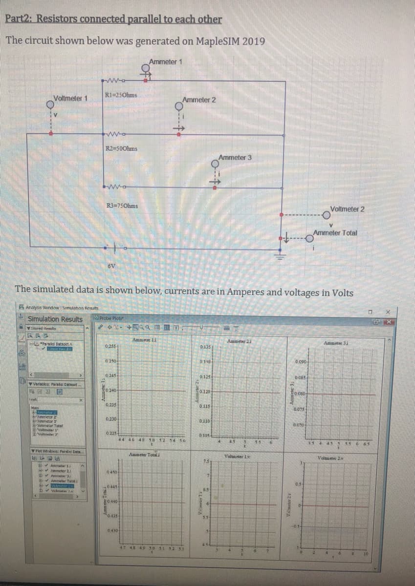
Transcribed Image Text:Part2: Resistors connected parallel to each other
The circuit shown below was generated on MapleSIM 2019
Ammeter 1
RI=25Ohms
Voltmeter 1
Ammeter 2
R2=500hms
Ammeter 3
R3=75Ohms
Voltmeter 2
V.
Ammeter Total
6V
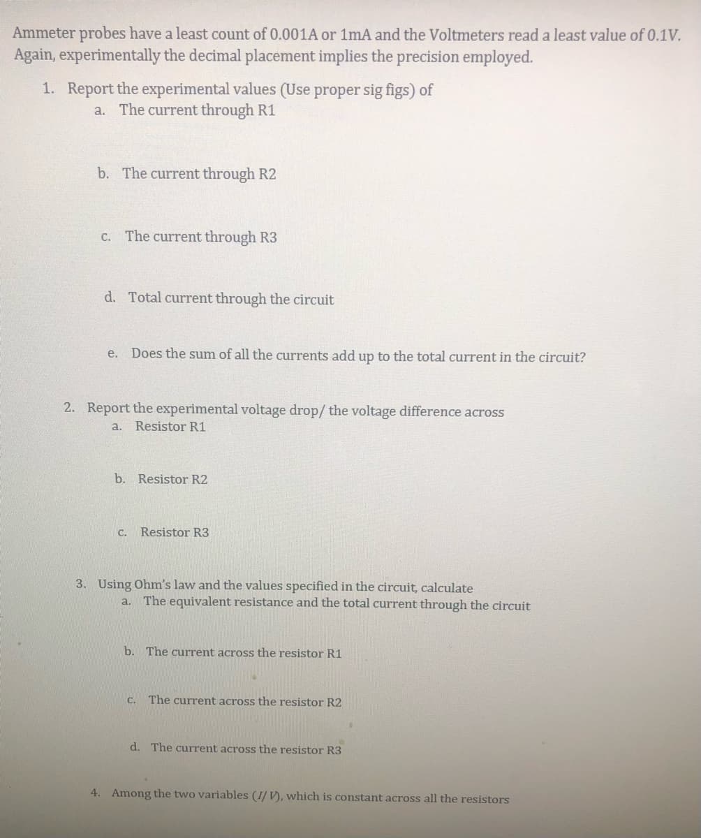
The simulated data is shown below, currents are in Amperes and voltages in Volts
K Analysis Vindow: Simulation Reauts
Simulation Results
Probe Plots
Slored teks
Ammeter Li
Ammeter 21
Ammeter 3.
HA Paralel DatsotA
tet
0.255
0.135
0210-
010
0.080
0245-
0125
0.085
Variacies: Parale Dataset .
0240
0.120
0.080
0.235
0.115
Mein
Ammeter 1
Ammeter 2
Ammeter
Ammetar Totar
D'Voltmster 1
0.075
0,230-
0.110
0 225-
44 46 48 SU 52 54 16
0 105
4.
45
354 43 5 15 6 65
1.5
in
6. 65
V Flot Wndows: Perelel Datn
Ammeter Total
Voltmeter 1.v
Volmeter 2v
7.5
Ammeter 1.
mmeter 2.1
D Amete 3.1
Amater Tatl.
okmettr
0410
0.5
0445-
Vlmat 2.N
5.5
20440
0.435
5.5
0430-
45
47 48 49 50 SL 52 5.5
10
Transcribed Image Text:Ammeter probes have a least count of 0.001A or 1mA and the Voltmeters read a least value of 0.1V.
Again, experimentally the decimal placement implies the precision employed.
1. Report the experimental values (Use proper sig figs) of
a. The current through R1
b. The current through R2
C. The current through R3
d. Total current through the circuit
e. Does the sum of all the currents add up to the total current in the circuit?
2. Report the experimental voltage drop/ the voltage difference across
a. Resistor R1
b. Resistor R2
C.
Resistor R3
3. Using Ohm's law and the values specified in the circuit, calculate
The equivalent resistance and the total current through the circuit
a.
b. The current across the resistor R1
C. The current across the resistor R2
d. The current across the resistor R3
4. Among the two variables (I/ V), which is constant across all the resistors
Expert Solution
This question has been solved!
Explore an expertly crafted, step-by-step solution for a thorough understanding of key concepts.

Step by step
Solved in 2 steps with 1 images

Recommended textbooks for you
Introductory Circuit Analysis (13th Edition)
Electrical Engineering
ISBN:
9780133923605
Author:
Robert L. Boylestad
Publisher:
PEARSON

Delmar's Standard Textbook Of Electricity
Electrical Engineering
ISBN:
9781337900348
Author:
Stephen L. Herman
Publisher:
Cengage Learning

Programmable Logic Controllers
Electrical Engineering
ISBN:
9780073373843
Author:
Frank D. Petruzella
Publisher:
McGraw-Hill Education
Introductory Circuit Analysis (13th Edition)
Electrical Engineering
ISBN:
9780133923605
Author:
Robert L. Boylestad
Publisher:
PEARSON
Delmar's Standard Textbook Of Electricity
Electrical Engineering
ISBN:
9781337900348
Author:
Stephen L. Herman
Publisher:
Cengage Learning
Programmable Logic Controllers
Electrical Engineering
ISBN:
9780073373843
Author:
Frank D. Petruzella
Publisher:
McGraw-Hill Education

Fundamentals of Electric Circuits
Electrical Engineering
ISBN:
9780078028229
Author:
Charles K Alexander, Matthew Sadiku
Publisher:
McGraw-Hill Education

Electric Circuits. (11th Edition)
Electrical Engineering
ISBN:
9780134746968
Author:
James W. Nilsson, Susan Riedel
Publisher:
PEARSON

Engineering Electromagnetics
Electrical Engineering
ISBN:
9780078028151
Author:
Hayt, William H. (william Hart), Jr, BUCK, John A.
Publisher:
Mcgraw-hill Education,