20 in. 28 in. -75 in.- c 12 in. E 12 in. 12 in. 20 in. 18 in. 24 in. 4500 lb н 22 in. 10 in.
20 in. 28 in. -75 in.- c 12 in. E 12 in. 12 in. 20 in. 18 in. 24 in. 4500 lb н 22 in. 10 in.

Related questions
Question
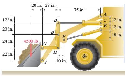
The motion of the bucket of the front-end loader shown is controlled by two arms and a linkage that are pin-connected at D. The arms are located symmetrically with respect to the central vertical and longitudinal plane of the loader; one arm AFJ and its control cylinder EF are shown. The single linkage GHDB and its control cylinder BC are located in the plane of symmetry. For the position and loading shown, determine the force exerted (a) by cylinder BC, (b) by cylinder EF.
Transcribed Image Text:20 in. 28 in.
-75 in.-
c 12 in.
E 12 in.
12 in.
20 in.
18 in.
24 in.
4500 lb
н
22 in.
10 in.
Expert Solution
This question has been solved!
Explore an expertly crafted, step-by-step solution for a thorough understanding of key concepts.

This is a popular solution!

Trending now
This is a popular solution!

Step by step
Solved in 6 steps with 8 images
