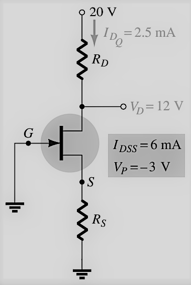
20 V = 2.5 mA IDQ RD VD=12 G I Dss =6 m Vp =-3 V


Q: Circuit : Design a circuit that has a total of 6 voltage measurement points. The voltage…
A:
Q: 1. What is the output voltage? 2. What is the main application of this circuit? R, = 2k R = 1k V =…
A:
Q: Design the circuit shown to obtain a dc voltage of +0.15 V at each of the drains of Q₁ and Q when…
A: Transistor:- It is a three terminal device that is used to amplify the input signal or regulate…
Q: 4. Calculate how many Volt the output voltage is and how many microamps the current on Rf is in the…
A: In an ideal op-amp, the input impedance is infinity and hence the current taken by it will be equal…
Q: The circuit in the figure shows the drain current and drain-source at the working point. Calculate…
A: MOSFET and JFET circuit are given in the figure shows Find the the drain current and drain-source.…
Q: -15V A voltage, v, to current, io, converter circuit is shown. Compete the design of the circuit by…
A: Given : In the above given question they have mentioned an operational amplifier circuit with…
Q: If the same input v, is applied on the two circuits in bellow determine v, for each one All 8V Ideal…
A: To solve above mentioned problem, one should have clear understanding of working of diode. A diode…
Q: 300 a 25 V -20 mV DC
A: Kirchhoff's current law: This law states that the sum of current flowing through a node is zero. So…
Q: Find the voltage Vout and the current I in the circuit shown in Figure 5. You can assume that the…
A:
Q: The total current drawn at the parallel combination of 10-ohms and 67-ohms resistors is 2 Amps.…
A: If two resistors R1 and R2 are in parallel than equivalent resistance is R1×R2R1+R2. power observed…
Q: For the circuit below, what will be the output voltage if the input is V₁ = 0.2 V? 470 ΚΩ W RF 2.4…
A:
Q: Question-3 For the voltage divider bias configuration of figure below, determine: 16 V a- IBQ b- Ico…
A: The given circuit is voltage divider bias configuration. Find the value of collector current, bias…
Q: In a common base connection, a = 0.95. The voltage drop across 2 k resistance which is connected in…
A: Given, α=0.95V2kΩ=2 V
Q: For the circuit shown below. Each of the digital voltmeter has a 10 MO internal resistance. Their…
A: As per the guidelines I have to do a maximum of 1 question so I request you to submit the remaining…
Q: 4) The circuit and transistor parameters are given as follows: Bß = 130, Ico = 0.2 mA, VA = 80 V, V,…
A:
Q: Self Test The equivalent resistance of the parallel resistors (20n and 50) equals 40. Use VDR and…
A: The phenomenon by which an electrical element obstructs the flow of current is known as resistance…
Q: For the voltage-divider configuration of the figure below: Sketch the DC equivalent circuit…
A: Brief description : In the above given question they have mentioned a voltage divider MOSFET circuit…
Q: Question 8 The given common-source stage is to be designed for a voltage gain of 10 VV with W = 40…
A:
Q: Arm resistances of Wheatstone bridge are R = 200 Q R, = 400 N R = 500 Q R = 600 2 Input is, E= 5 V.…
A:
Q: SCRS with a rating of 1000 V & 200 A are available to be used in a string to handle 6 KV & 1 KV. The…
A:
Q: 5 k2 IL 80 – 120 V 50 V 10 k2
A: From the given circuit the maximum and minimum Zener current is found below: For Vi=80 VI=80-505 KΩ…
Q: 4. a.) For the voltage-divider bias configuration shown below, determine: a. Ibq b. Icq c. Vceq d.…
A:
Q: Design a Wheatstone bridge circuit that satisfies the given conditions. Include all resistor values…
A: We need to design a Wheatstone bridge circuit that satisfies the given conditions: Vi=30030 mV,…
Q: Q-) For the Voltage -divider bias Configuration of Figure below determine @ Is. 6 Ice Øveco D Vc VE…
A:
Q: A series circuit consists of a 240-V source and 12-ohm, 20- ohm, and 16-ohm resistors. a. Find the…
A:
Q: Determine the current x in the 4-Q resistance of the circuit shown in the figure. 10 10 V 6A 24 V
A: According to the question we need to calculate the value of x.
Q: Calculate the maximum input voltage that will maintain the voltage across the load at 11 V when…
A: Voltage across the load (Vo or VZ) = 11 V R = 218 Ω RL = 990 Ω Maximum zener current, IZmax =…
Q: For the voltage divider bias JFET circuit shown, What is the drain current Ip if VD = 8V? VOD = 16V…
A: Given Vdd = 16v and Vd = 8v and Rd = 1kohm. find Drain Current ?
Q: Calculate the output voltage using the circuit of figure below for resistor components of value…
A: Amplifier is an electronic device whose output is amplified version of the input signal. The…
Q: b) For the circuit shown in Figure (1) draw the output voltage if i= Scint. 2kQ 4kQ ww www 1kQ Vi.…
A:
Q: cc-15V 오 R1=20KN° Rc 2KN c=2 R: = 80KN° RE = 1KN
A:
Q: 1. What is the output voltage? 2. What is the main application of this circuit? R, = 2k R = 1k V =…
A:
Q: 4. Find the Vo and Va in the circuit below. 4V, 50 20 2V 15V VA Vo 8V
A:
Q: 1. Determine the output voltage for each circuit (a), (b), (c), and (d) below. 1 k2 10 k2 +12V 8 kn…
A: Since you have posted the multiple questions so we are supposed to answer 3 subpart.
Q: 8) For a source follower type voltmeter r= 10 k, gm=0.003 mho, R, = 15 kand R = 1800. How much…
A: Given values: rd= 10 kΩ, gm=0.003 mho, Rs=15 kΩRm=1800 Ω, Vin= 1 V
Q: Q6/ For the voltage divider bias circuit, Determine the following: (Using exact method) 18 V a. Ic.…
A:
Q: 1. Construct the BJT circuit shown in Figure 1 on your project board with VBB = 12V and Vcc= 12V.…
A:
Q: en the circuits below, the voltage at R1 is equal to V for the following paramete R1 = 700 2; R2 =…
A:
Q: Sketch the ouput voltage (Vo) for the circuit and the input voltage (V) show in figure (3
A: A diode is a two terminal PN junction device, the two terminals of a diode are anode and cathode.…
Q: a. What is V3 when Vbe = 0.7V, beta = 100, R2 = 1k, Vce(sat) = OV, V1 = 3V and R1 = 0? b. What is V3…
A: The voltage at emitter terminal can be calculated by applying the kirchhoff's voltage law to the…
Q: If A = 5V and B = 5V, find Vo. (VDD = 5V, R = 500, VTH = 1V, and k = 50 mA/V²). Put at least 2…
A: The circuit diagram is shown below, Where,A=B=5VVDD=5VR=500ΩVTH=1Vk=50mA/V2
Q: 1. Design the voltage divider of Figure 1 such that VRI = 4VR2. 20 V Figure 1
A:
Q: Consider the following circuit diagram: 3 V 1 V 2 V WWW 40 ΚΩ ww R 2o-WW I V 160 ΚΩ - 20 ΚΩ -15 V…
A:
Q: 5) Give a voltage value for v; and another voltage value for (V) voltage source (v;> V). Calculate…
A: I have explained in detail, Given circuit is Negative Biased shunt positive clipper
Q: Q2 /A)- What the range of developed output voltage for the circuit of .figure below if the 1= 0.0067…
A: Output voltage range of inverting op amplifier. Feedback element is variable. V+ = V- = 0V using…
Q: (a) A current of 2.0 ± 0.01 A flows through a resistance of 150 Q with a tolerance of + 0.3 Q in a…
A:
Q: 4. What is the current total current (IParallel) flowing in the circuit below and what is the…
A: The circuit is shown below: In the above circuit, the resistances are connected in parallel, and…
Q: Vbe(on)=0.7V, Vbe(sat)=0.9V, Vce(sat)=0.2V, ß=200. Draw the load line of the circuit. Show operating…
A: Vbe(on)=0.7V, Vbe(sat)=0.9V, Vce(sat)=0.2V, ß=200. Draw the load line of the circuit. Show operating…
Determine values of drain-resistor and source-resistor of this circuit.

Step by step
Solved in 2 steps with 2 images


- Reply as soon as posible 1) For the circuit in Figure 1, set up the supernode equation. Response format: Ava ± Bvb ± Cvx = D 2) For the circuit in Figure 1, set up the auxiliary equation of the supernode. Response format: Ava ± Bvb ± Cvx = D 3) For the circuit in Figure 1, set up the equation for the remaining node. Response format: Ava ± Bvb ± Cvx = DTOTAL IMPEDANCE FIND CIRCUIT ( NEED NEAT HANDWRITTEN SOLUTION ONLY OTHERWISE DOWNVOTE).notes: u(t) = 0 for t<0 = 1 for t>=0 u(-t) = 1 for t<0 = 0 for t>=0 Assume components are ideal, unless otherwise specified. Assume circuits had been on/running for a long time before a change in the circuit happens, unless otherwise specified. Allow for round off errors for the final answer that you get (vs. the indicated final answer)
- Circuits 2:Source Transformation (AC) Pls show full and clean solution tnxCan you find V1, V2, V3 and V4 with node analysis WITHOUT USING SUPERNODE TECHNIQUE. y value is 4.( NEED only handwritten solution please otherwise downvote).C = 5 nF, L = 79.16 mH, R = 1.99 kΩ, ωc1 = 39246.1 rad/s, ωc2 = 64378.8 rad/s Please show all steps clearly, thank you.