24. Refer to Table 12.6 and Figure 12.12 attached. What would be the fatigue damage according to the PCA design method for 50,000 repetitions of a 26-kip single axle, a subgrade k=200 psi/in, a flexural strength=600 psi, and a 6.5-inch thick concrete slab without concrete shoulders? Select the best answer. a. 0.0 b. 0.5 c. 0.75 d. 10.0
24. Refer to Table 12.6 and Figure 12.12 attached. What would be the fatigue damage according to the PCA design method for 50,000 repetitions of a 26-kip single axle, a subgrade k=200 psi/in, a flexural strength=600 psi, and a 6.5-inch thick concrete slab without concrete shoulders? Select the best answer. a. 0.0 b. 0.5 c. 0.75 d. 10.0

Traffic and Highway Engineering
5th Edition
ISBN:9781305156241
Author:Garber, Nicholas J.
Publisher:Garber, Nicholas J.
Chapter20: Design Of Rigid Pavements
Section: Chapter Questions
Problem 9P

Related questions

Question
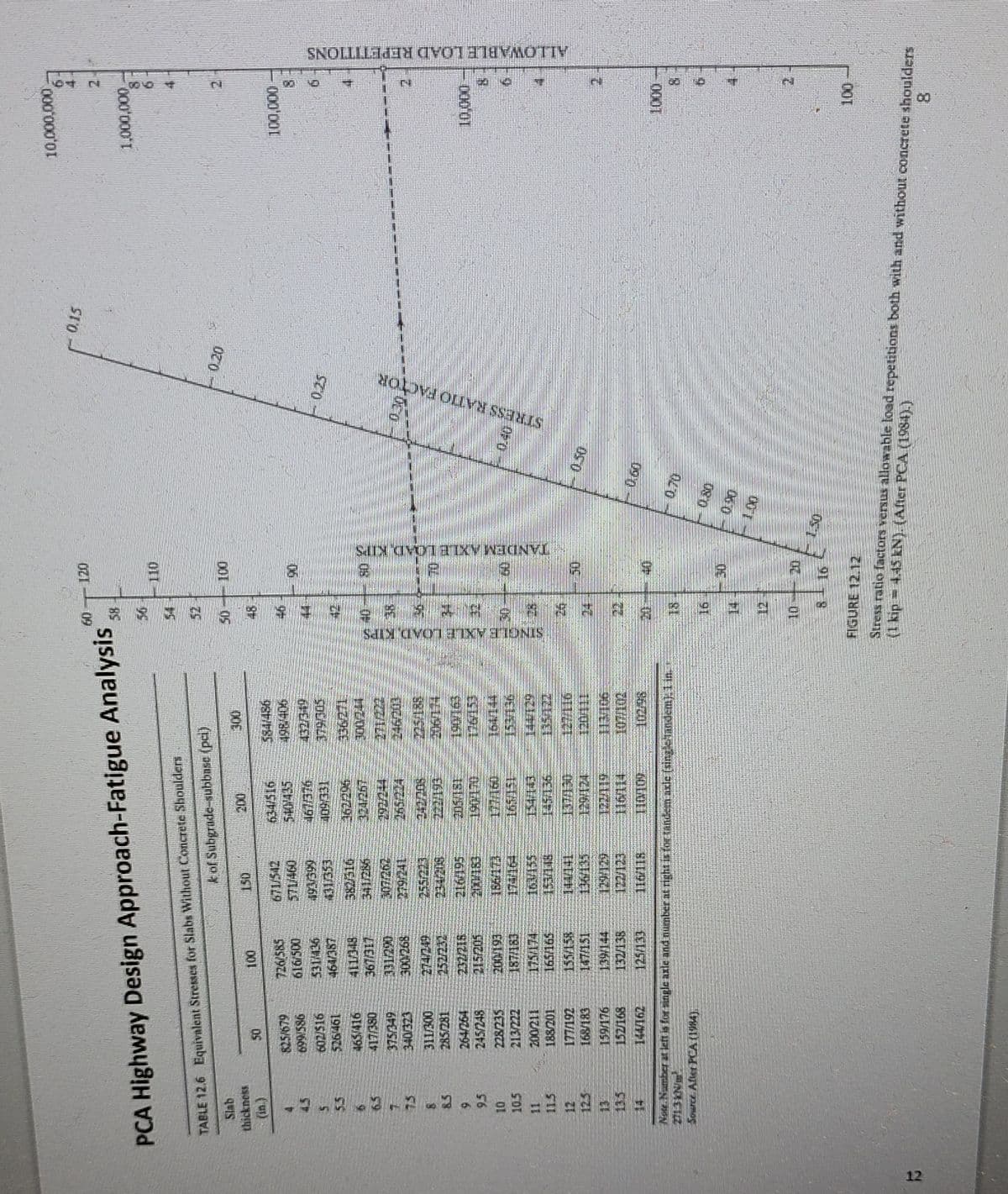
24. Refer to Table 12.6 and Figure 12.12 attached. What would be the fatigue damage according to the PCA
design method for 50,000 repetitions of a 26-kip single axle, a subgrade k=200 psi/in, a flexural
strength=600 psi, and a 6.5-inch thick concrete slab without concrete shoulders? Select the best answer.
a. 0.0
b. 0.5
c. 0.75
d. 10.0
25. Refer to Table 12.8 and Figure 12.13 attached. What would be the erosion damage according to the PCA
design method for the same conditions stated in Question 24 above? Select the best answer.
a. 0.0
b. 0.125
c. 0.835
d. 10.0
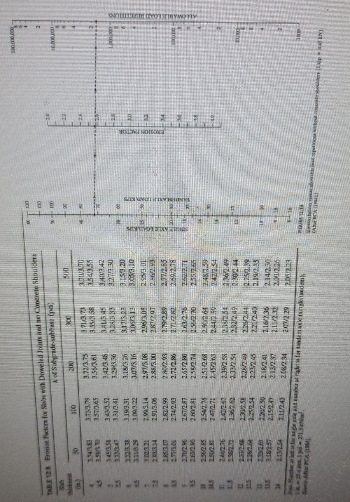
Transcribed Image Text:TABLE 12.8 Erosion Factors for Slabs with Doweled Joints and no Concrete Shoulders
k of Subgrade-subbase (pci)
Slab
thickness
(in.)
5
55
9
6.5
7
1.2
5
10
10.5
11
13.5
50
3.74/3.83
3.59/3.70
3.45/3.58
3.333.47
3.22/3.38
3.11/3.29
3.02/3.21
2.93/3.14
2.85/3.07
2.77/3.01
2.70/2.96
2.63/2.90
2.56/2.85
2.50/2.81
2.442.76
2.182.57
2.132.54
100
3.73/3.79
3.57/3.65
3.43/3.52
3.31/3.41
3.19/3.31
3.09/3.22
2.99/3.14
2.91/3.06
2.82/2.99
2.74/2.93
2.67/2.87
2.60/2.81
2.422.67
2.36/2.62
2.30/2.58
2.20/2.50
2.15/2.47
2.11/243
200
3.72/3.75
3.56/3.61
3.42/3.48
3.29/3.36
3.18/3.26
3.07/3.16
2.97/3.08
2.88/3.00
2.80/2.93
2.72/2.86
2.65/2.80
2.58/2.74
2.51/2.68
2.45/2.63
2.39/2.58
2.33/2.54
2.28/2.49
2.23/2.45
2.18/2.41
2.13/2.37
2.08/2.34
300
3.71/3.73
3.55/3.58
3.41/3.45
3.28/3.33
3.17/3.23
3.06/3.13
2.96/3.05
2.87/2.97
2.79/2.89
2.71/2.82
263/2,76
2.56/2.70
2.50/2.64
2.44/2.59
2.38/2.54
2.32/2.49
2.26/2.44
2.21/2.40
2.16/2.36
2.11/2.32
207/2.29
3.70/3.70
3.54/3.55
3.40/3.42
3.27/3.30
3.15/3.20
3.0573.10
2.95/3.01
2.86/2.93
2.77/2.85
2.69/2.78
2.62/2.71
2.36/2.49
2.25/2.39
2.19/2.35
2.14/2.30
2.09/2.26
2.05/2.23
in. ≈ 25 2 mm. 1 pá – 271.3 kN/m²³,
Now Number at left is for sine axie and number at right is for tandem axle (single/tandem).
Source After PCA (1984).
#
N
NINY UVOTTINTIONIS
P
2
10
2
2
SIIN GYOTTINN KJŪNVI
HODVINO SOMA
LLLLLL
14
__IT=
1.8
u
ILLI
2
S
4
IN
9
100.000,000
110,000,000
1.000.000
195
****
⠀⠀
H
THE
10000
1000
FIGURE 12.13
LADer PCA (1SILY
Erosion factors versus allowable load repetitions without concrete shoulders (1 kip – 4.45 KN).
AHWABU. LOAD RIPETITIONS
Transcribed Image Text:R
PCA Highway Design Approach-Fatigue Analysis
TABLE 12.6 Equivalent Stresses for Slabs Without Concrete Shoulders
k of Suhgrade-suhbnsc (pci)
Slab
thickness
75 -1.
5.5
8.5
9
9.5
10
10.5
50
825/679
985/669
602/516
526461
465/416
417/380
375/349
340/323
311/300
285/281
264/264
245/248
228/235
213/222
200/211
188/201
168/183
159/176
100
726/585
616/500
531 436
464/387
411348
367/317
331220
300/2.68
274/249
252/232
215/205
200/193
187-183
165/165
155/158
147/151
150
671/542
571/460
1911399
131653
382/316
300/202
216195
2018
13655
200
634/516
5407435
92E/191
109331
186502
300
379505
139144
132/136
17123
125/133
116-118
Note. Number at left is for single axle and number at right is for tandemn axle (singlexandem). 1 in.
Source. After PCA (1984).
107002
SINGLE AXLE LOAD, KIPS
60
F
48
51
2
S
A
20
12
In
7
15
Sm
120
3
S
TANDEM AXLE LOAD KITS
STRESS RATIO FACTOR
0.20
0.15
10,000,000
NAO
1,000,000
4
100,000
60
2
11
10,000
1947
N
1000
26
12
N
100
ALLOWABLE LOAD REPETITIONS
FIGURE 12.12
(1 kip = 4.45 KN). (After PCA (1984).)
Stress ratio factors versus allowable load repetitions both with and without concrete shoulders
8
Expert Solution
This question has been solved!
Explore an expertly crafted, step-by-step solution for a thorough understanding of key concepts.

Step by step
Solved in 3 steps with 2 images

Knowledge Booster


Learn more about
Need a deep-dive on the concept behind this application? Look no further. Learn more about this topic, civil-engineering and related others by exploring similar questions and additional content below.Recommended textbooks for you
Traffic and Highway Engineering
Civil Engineering
ISBN:
9781305156241
Author:
Garber, Nicholas J.
Publisher:
Cengage Learning
Traffic and Highway Engineering
Civil Engineering
ISBN:
9781305156241
Author:
Garber, Nicholas J.
Publisher:
Cengage Learning