
Elements Of Electromagnetics
7th Edition
ISBN: 9780190698614
Author: Sadiku, Matthew N. O.
Publisher: Oxford University Press
expand_more
expand_more
format_list_bulleted
Question
For the beam shown in Figure 1, determine the shear stresses at points “a” and “b” at
section n-n.

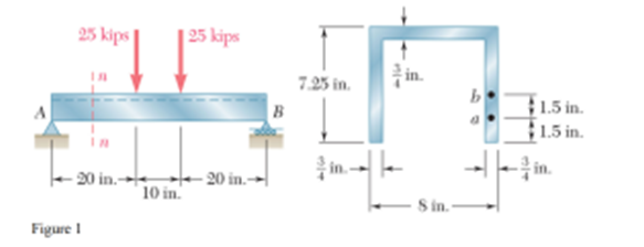
Transcribed Image Text:25 kips
20 in.-
Figure 1
10 in.
25 kips
-20 in.
B
7.25 in.
3514
-8 in.
b
MIT
1.5 in.
1.5 in.
Expert Solution

This question has been solved!
Explore an expertly crafted, step-by-step solution for a thorough understanding of key concepts.
This is a popular solution
Trending nowThis is a popular solution!
Step by stepSolved in 2 steps with 3 images

Knowledge Booster
Learn more about
Need a deep-dive on the concept behind this application? Look no further. Learn more about this topic, mechanical-engineering and related others by exploring similar questions and additional content below.Similar questions
- Q2: A shear force of 5 kips is acting On a T-shaped cross section shown in figure Question 2, determine the shear stress a. In the Web at point A b. and in the flange at point A Note: Centroid is to be calculated only from the reference line shown in the figure. 5 in 3in inarrow_forwardshow all steps/solution plzarrow_forwardThe cross-sectional dimensions of the beam shown in the figure are r = 113 mm and r;= 87 mm. Given M₂ = 16 kN-m, a = 37º, and ß = 53º, what are the bending stresses at points Hand K? H To a Part 1 Incorrect. Find the moment of inertia for a solid circular cross-section of radius 113 mm, then subtract the moment of inertia for a solid circular cross-section of radius 87 mm. Find the area moment of inertia for the cross-section about the z axis. Į₂ = mmª 7arrow_forward
- In the figure shown, the aluminum strut has a cross-sectional area in the form of a cross. If it is subjected to the moment M= 8 kN.m: 1) determine the bending stress acting at points A and B, 2) show the results acting on a stress distribution diagram.arrow_forwardQ2 The internal bending moment in a beam with a cross sectional area shown in the figure is 500a in the direction shown. Nom Find: a) The centroid of the cross sectional area and, b) the maximum tensile and compressive normal stresses. Make a sketch showing the stress distribution A A -35 mm C2 100 mm C1 = ỹ 5 G0 Na m 25 mm B 50 25 50. mm 'mr mmarrow_forwardThe figure shows the cross-section of a beam that is composed of a wide-flanged structural profile, whose specification is indicated in the figure, and two steel plates, joined by means of screws, placed in pairs with a longitudinal separation of 20 cm . If the beam is subjected to a vertical shear force of 25 KN, determine the shear stress supported by each bolt in the topsheet. Please add the free diagram body.arrow_forward
- A simply supported beam (i.e., with a pin support at point A and a roller support at point D) is subjected to the external loadings shown in the figure. The cross- soction is shown to the right of the beam. 10 IN 10 KN mm 10mm Determine the shear stress developed in the cross-section n-n at point E on the web, 2m S0mmarrow_forward1. Compute the maximum shear stress and maximum flexural stress of the beam shown in the figure. 20 ΚN 2 m 200 mm 25 mm 150 mm 5 KN/m 50 mm 15 KN/m 100 mm 5 KN/m 300mm 1.5 m 3.5 marrow_forward
arrow_back_ios
arrow_forward_ios
Recommended textbooks for you
- Elements Of ElectromagneticsMechanical EngineeringISBN:9780190698614Author:Sadiku, Matthew N. O.Publisher:Oxford University PressMechanics of Materials (10th Edition)Mechanical EngineeringISBN:9780134319650Author:Russell C. HibbelerPublisher:PEARSONThermodynamics: An Engineering ApproachMechanical EngineeringISBN:9781259822674Author:Yunus A. Cengel Dr., Michael A. BolesPublisher:McGraw-Hill Education
- Control Systems EngineeringMechanical EngineeringISBN:9781118170519Author:Norman S. NisePublisher:WILEYMechanics of Materials (MindTap Course List)Mechanical EngineeringISBN:9781337093347Author:Barry J. Goodno, James M. GerePublisher:Cengage LearningEngineering Mechanics: StaticsMechanical EngineeringISBN:9781118807330Author:James L. Meriam, L. G. Kraige, J. N. BoltonPublisher:WILEY

Elements Of Electromagnetics
Mechanical Engineering
ISBN:9780190698614
Author:Sadiku, Matthew N. O.
Publisher:Oxford University Press

Mechanics of Materials (10th Edition)
Mechanical Engineering
ISBN:9780134319650
Author:Russell C. Hibbeler
Publisher:PEARSON

Thermodynamics: An Engineering Approach
Mechanical Engineering
ISBN:9781259822674
Author:Yunus A. Cengel Dr., Michael A. Boles
Publisher:McGraw-Hill Education

Control Systems Engineering
Mechanical Engineering
ISBN:9781118170519
Author:Norman S. Nise
Publisher:WILEY

Mechanics of Materials (MindTap Course List)
Mechanical Engineering
ISBN:9781337093347
Author:Barry J. Goodno, James M. Gere
Publisher:Cengage Learning

Engineering Mechanics: Statics
Mechanical Engineering
ISBN:9781118807330
Author:James L. Meriam, L. G. Kraige, J. N. Bolton
Publisher:WILEY