3. Consider again the system in Fig. 1. The plant transfer function in the frequency domain is 100 G(jw) = (jw + 2) (jw + 4)(jw +10) Fig. 2 shows a Nyquist contour for G(jw). Nyquist Diagram 1.5 0.5 -0.5 -1.5 -1.5 -0.5 0.5 1.5 Real Axis Figure 2: Nyquist Contour (i) system becomes marginally stable and the practical range of safe operating gains for the proportional controller. Apply the Nyquist criterion to find the gain Kp at which the closed loop Find the gain margin of the system when the operating gain of the controller (ii) K, = 2. Use Fig. 2 to read the required values off the plot. Imaginary Axis
3. Consider again the system in Fig. 1. The plant transfer function in the frequency domain is 100 G(jw) = (jw + 2) (jw + 4)(jw +10) Fig. 2 shows a Nyquist contour for G(jw). Nyquist Diagram 1.5 0.5 -0.5 -1.5 -1.5 -0.5 0.5 1.5 Real Axis Figure 2: Nyquist Contour (i) system becomes marginally stable and the practical range of safe operating gains for the proportional controller. Apply the Nyquist criterion to find the gain Kp at which the closed loop Find the gain margin of the system when the operating gain of the controller (ii) K, = 2. Use Fig. 2 to read the required values off the plot. Imaginary Axis

Introductory Circuit Analysis (13th Edition)
13th Edition
ISBN:9780133923605
Author:Robert L. Boylestad
Publisher:Robert L. Boylestad
Chapter1: Introduction
Section: Chapter Questions
Problem 1P: Visit your local library (at school or home) and describe the extent to which it provides literature...

Related questions

Question
Course is control system...
Transcribed Image Text:3.
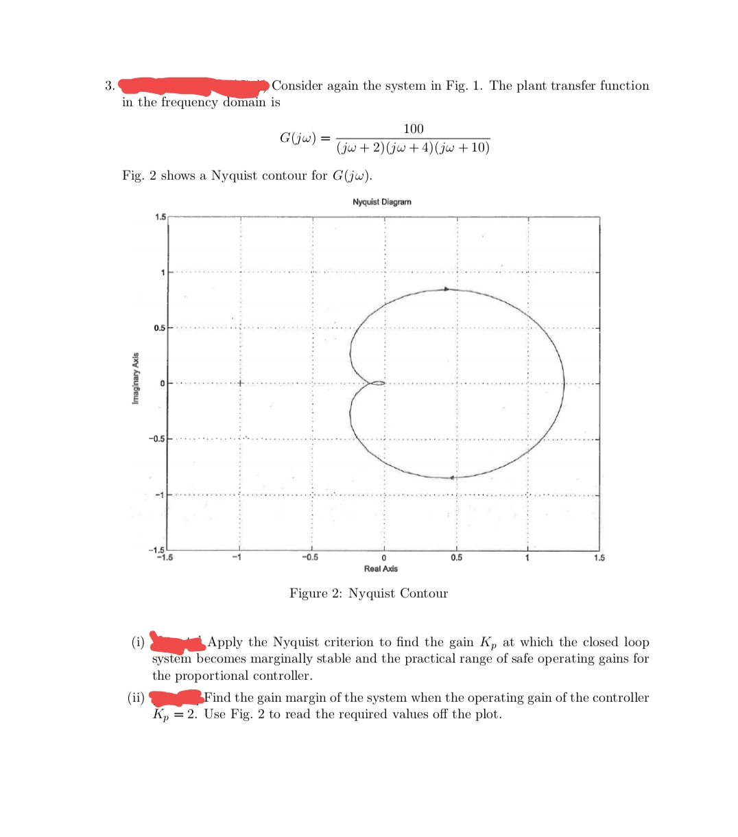
Consider again the system in Fig. 1. The plant transfer function
in the frequency domain is
100
G(jw) =
(jw + 2) (jw + 4)(jw + 10)
Fig. 2 shows a Nyquist contour for G(jw).
Nyquist Diagram
1.5
0.5
-0.5
-1.5
-1.5
-0.5
0.5
1.5
Real Axis
Figure 2: Nyquist Contour
(i)
system becomes marginally stable and the practical range of safe operating gains for
the proportional controller.
Apply the Nyquist criterion to find the gain Kp at which the closed loop
Find the gain margin of the system when the operating gain of the controller
(ii)
K, = 2. Use Fig. 2 to read the required values off the plot.
Imaginary Axis
Expert Solution
This question has been solved!
Explore an expertly crafted, step-by-step solution for a thorough understanding of key concepts.

Step by step
Solved in 3 steps with 3 images

Knowledge Booster


Learn more about
Need a deep-dive on the concept behind this application? Look no further. Learn more about this topic, electrical-engineering and related others by exploring similar questions and additional content below.Recommended textbooks for you
Introductory Circuit Analysis (13th Edition)
Electrical Engineering
ISBN:
9780133923605
Author:
Robert L. Boylestad
Publisher:
PEARSON

Delmar's Standard Textbook Of Electricity
Electrical Engineering
ISBN:
9781337900348
Author:
Stephen L. Herman
Publisher:
Cengage Learning

Programmable Logic Controllers
Electrical Engineering
ISBN:
9780073373843
Author:
Frank D. Petruzella
Publisher:
McGraw-Hill Education
Introductory Circuit Analysis (13th Edition)
Electrical Engineering
ISBN:
9780133923605
Author:
Robert L. Boylestad
Publisher:
PEARSON
Delmar's Standard Textbook Of Electricity
Electrical Engineering
ISBN:
9781337900348
Author:
Stephen L. Herman
Publisher:
Cengage Learning
Programmable Logic Controllers
Electrical Engineering
ISBN:
9780073373843
Author:
Frank D. Petruzella
Publisher:
McGraw-Hill Education

Fundamentals of Electric Circuits
Electrical Engineering
ISBN:
9780078028229
Author:
Charles K Alexander, Matthew Sadiku
Publisher:
McGraw-Hill Education

Electric Circuits. (11th Edition)
Electrical Engineering
ISBN:
9780134746968
Author:
James W. Nilsson, Susan Riedel
Publisher:
PEARSON

Engineering Electromagnetics
Electrical Engineering
ISBN:
9780078028151
Author:
Hayt, William H. (william Hart), Jr, BUCK, John A.
Publisher:
Mcgraw-hill Education,