3. Solve for Ipand Va +20 V Si Si Si Si V 4.7 kN
Q: Vs 2H 42 52 3MCT) 낮 육 V4 ㅁ u 222
A: Given data, Circuit diagram is given as,
Q: RL IL b 1.5 kN R3 6.8 kN R21.2 kN E+ 8 V R3 1.0 kN figure d
A:
Q: 1 diagrams of both the direct forms I and II simulation diagrams for the systems with the following…
A:
Q: GHIS) s(S+2) (St4)
A:
Q: 5. I =_mA %3D R, = 15 kn %3D E = 1000 V R2 = .5 M2. %3D
A: When two resistance connected in series then current flowing through both the resistance is same but…
Q: Perporm the in dicated apera tions. 3) BB14 + 613.812= 12
A: To add two number of different bases first convert them into common base most preferably decimal…
Q: 16 A wwww 40 n 12 A 10 0 20 n 2 A -wwW- -WWW
A:
Q: Obtain the equivalent resistance using star delta transformation, between E and F for the circu 500…
A: The delta connection between points A, C, G is transformed into star connection as shown below, and…
Q: 20n 10on E RL 2. BOLVE FOR PMAX +
A:
Q: 5. Find lo using Nodal Analysis 4 kM 2 mA 3 kN 12 V 6 kN C2 kN
A:
Q: R. 10 kQ VBIAS 8.0 V ideal diyot modelini kullanarak oluşturulan şekildeki devrede ölçülen akım…
A: For ideal diode voltage across it is zero when it is on , zero forward resistance and voltage…
Q: 202 V1 + 500 mA 25L 80r 100v
A:
Q: R₁ mis R4 R un. R R un m R un I V₂ 20/01 | Hvis/ H (H(jw)
A: When input is applied on inverting terminal with negative feedback then it is called inverting…
Q: (A) IN (1) RN NORTONS EQUIVALE
A:
Q: 6. L= . E = 200 V- R, = 150 0 R2 = 300 0 %3D %3D
A:
Q: Determine the output voltage (Vo) and current (I) for the circuit shown below. +16 V Si 4.7 k2 12 V
A:
Q: 4) Given figure is the representation of which toggle switch 254 5.08 LA 2.54 PCB LAYOUT L M6 DPDT…
A: The given figure in the question shows the representation and OCB layout of a toggle switch. We need…
Q: A practical source supplies IL =2 A to a 10-ohm load and IL =1 A to a 50-ohm load. 7. Determine its…
A: The solution can be achieved as follows
Q: 5) Solve for ia 2 V 2Ω 9 V 4Ω 0.5 A
A: Using source transformation convert voltage source and current source with equivalent voltage…
Q: Q1: for the figure, find re, Zi, Zo, Av, and Ai 22 V 5.6 k2 330 k2 Cc V 0 B=100 ro= 20k2 Z; 1.2 k2…
A:
Q: • Calculate the output voltage and Zener current for R₁=1kQ. (Solution: V=11.3 V; 1₂-36 mA) Q₁…
A: This is a transistor series regulator . zener diode provides the reference voltage. Q1 is an npn…
Q: For the following circuit in the figure below. Determine V,-V, (in units of V) for a = 41.9 V. 3.…
A:
Q: If R1 in the figure is open, the voltage is Vce +10 V R 10 kf? Rc 1.0 kl R2 4.7 kfl RE 470 n
A: Using KVL in input loop we will find base current , Based on the base current we will find collector…
Q: D3 D4 IR +12V Vo ID R4 5.6k2 Calculate: a. Current ID b. Voltage at D4 (VD4) c. Output Voltage (VO)…
A: In this question, We need to determine the diode current, voltage across the diode D4 and output…
Q: Find the equivalent resistance across the terminal 452 wwww 202 40 6023 www 892 wwww 202 892
A: The given circuit can be drawn as shown below. It is asked to calculate the equivalent resistance…
Q: Оp Amp H.W) You have 5 voltage inputs (V1...5) and you wish to calculate 4(V1 + V2 + V3) – 2(V4 +…
A: Op-amp- Op-amp is a linear analog IC having 8-pins. It is fabricated using VLSI.When op-amp is used…
Q: What is wrong with this circuit? * R12 10 kn + 24 V D, 1N4744A 4.790 v R2 2.5 kn RL 15 V The zener…
A: PURPOSE OF ZENER DIODE: To conduct significant current in reverse bias. To withstand for large…
Q: Qi For the following block oliagreum , Prove Het we Can detect fict) ancl fact) fit) LPF 4 LPF 3.…
A:
Q: MUX 0 MUX of 1 For the circuit shown in the given figure, which one of the following options…
A: This is MUX circuit. For this circuit, find the output expression ?
Q: 1. Find the range of K for the stability of each systemin the figures below R(s) + K C(s) (s + 2)…
A:
Q: Q6 L(cosh at) is equal to a) b) S c) s²-a d) None A O B O C OD
A:
Q: 3s+25 y=C-! s2+6s+13
A:
Q: 1. Find the following a. VL= b. Vc=. c. IRE d.lc=
A: As per the guidelines it is instructed to solve first three subparts for multiple subparts question.…
Q: R R Ief Ide 9 A 21 - R. R R ER 8 A h R R O A) 8 O B) 9 O 9 4 O D) 6 O E) 10
A: KCL: According to Kirchhoff's current law, the sum of current entering at a particular node=Sum of…
Q: By using Superpasition Pindthe Current threg 4 Resistor of this figure. Ric24n Es48U Rz=12. R3=452
A: To solve above problem, one should know about superposition theorem. It states that in any linear…
Q: Using the principal of superposition determine the current ix in the circuit shown in figure.
A: According to the Principle of superposition, the net response caused by two or more active elements…
Q: 1. For the circuit below, determine the following: a) Ic and VCE 16 V 1510 ΚΩ Iso Ico • 1.8 ΚΩ Vc…
A:
Q: Determine the approximate value of Ipss of the given circuit belo VDD 20V $2.1ka Q1 v, V, = - 4.5V…
A: In this question, choose the correct option What is value of IDSS We know Drain current ID =…
Q: 5. I =_mA R, = 15 kn %3D E = 1000 V R2 = .5 MQ. %3D
A: The solution is given below
Q: 1.0 ΚΩ 2.0 ΚΩ +12 1.8 ΚΩ 1.5 ΚΩ R₂ · 1.0 ΚΩ ID = 2 mA VGSOFF = -6 V Determine a) Vas b) 9m c) A
A:
Q: 1ちV -1ov 9k oH M ひkoH alpha= o.998 a zin T. din ro=lMohM 10 rul C2 Inf Vout * Calculate the Value of…
A:
Q: r2 a, C/m?. The volu (in C/m³) at r= 3.4 is Select one: O 95.20 71 40
A:
Q: 1ちV -1ov 9k oH M alphas o.998 a zin din ro=lMohM 10 rul C2 Inf Vout * Calculate the Value of Zi, Zo,…
A:
Q: 1. 25ul-t)V +. 352 1) ZA Solve for Ux (t). to
A: Given,
Q: 1B4B42 D1 V1 50 Vrms 60 Hz C1 RL 0° 1000µF 2500 (+2
A: Given: The circuit provided with 4 diodes connected in bridge form and a capacitor with polarity…
Q: V2 100nF VR 520° V 300n f=10 kHz What is the phasor voltage VR?
A:
Q: 12 k. 15 kN 36 V 118 mA 60 k2 VAB Select one: O a. Rth= 24 k O b. Rth= 75 k O C. Rth= 25 k O d. Rth=…
A: Short circuit the voltage and open circuit the current to obtain the value of Thevenin resistance.…
Q: R R-A VIN) O A2 VOUT VIN(+) O R R+ 4 Figure Q2 (a)
A: Given information: This solution is given.
Q: Q1. Find the equivalent resistance at terminals a-b of each circuit in Figure Q1. 100 75 0v 122 20 2…
A:
3.Solve for Id and Vo
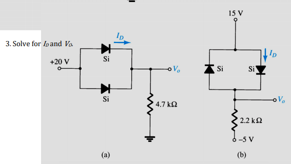
Step by step
Solved in 2 steps
- find p4+p5 power . it is so urgent.You have just walked into a room where electrical engineers were analyzing circuits. They wrote two equations on the whiteboard that represent Kirchhoff's loop law for a multi-loop circuit: E1-IaRa-IbRb=0 IbRb+E2=0 You aren't sure if the equations are correct (maybe the engineers were discussing impossible circuits), but you decide to learn about the circuit that is represented by the two equations above. Assume the symbols for current are unknown, but the EMFs and the resistances are known. The EMFs and resistances are positive as usual. Known: E1 , E2 , Ra , Rb Draw the circuit diagram (using the correct symbols for batteries and resistors) that corresponds to the loop law equations above. You will add more and more to this diagram as this problem goes on, so make it large. On your diagram, draw and label arrows next to each resistor to indicate the amount and direction of conventional current. Make your directions and labels consistent with the loop equations. For example, use iA…Consider the circuit in the given figure. Find the equivalent resistance at terminals: (a) a-b, (b) c-d. Assume R1 = 10 Ω and R2 = 90 Ω. The equivalent resistance at terminal a-b is ______ Ω. The equivalent resistance at terminal c-d is ________Ω.
- Find the Thévenin equivalent resistance RTH that drives R4 when E=20 V, R1=16 , R2=19, R3=25 and R4=10.a)Write the relationship between V1 , R1 , Rc and Ic .b) Write the relationship between V2 , R2 , Rc and Ic .c) Write the relationship between V3 , R3 , Rc and Ic .d) Determine the values of Rc and Ic .e) Determine the value of R3 .Find the equivalent resistance of the circuit ofFigure P2.59 by combining resistors in series and inparallel. R0 = 4 , R1 = 12 , R2 = 8 , R3 = 2 ,R4 = 16 , R5 = 5 .