-36. The compound beam is fixed at A, pin connected a B. and supported by a roller at C. Draw the shear and moment diagrams for the beam. 2 kN 3 kN/m B
-36. The compound beam is fixed at A, pin connected a B. and supported by a roller at C. Draw the shear and moment diagrams for the beam. 2 kN 3 kN/m B

Mechanics of Materials (MindTap Course List)
9th Edition
ISBN:9781337093347
Author:Barry J. Goodno, James M. Gere
Publisher:Barry J. Goodno, James M. Gere
Chapter9: Deflections Of Beams
Section: Chapter Questions
Problem 9.5.43P: Find required distance d (in terms of L) so that rotation Ss= 0 is due to M and q loadings applied...

Related questions
Question
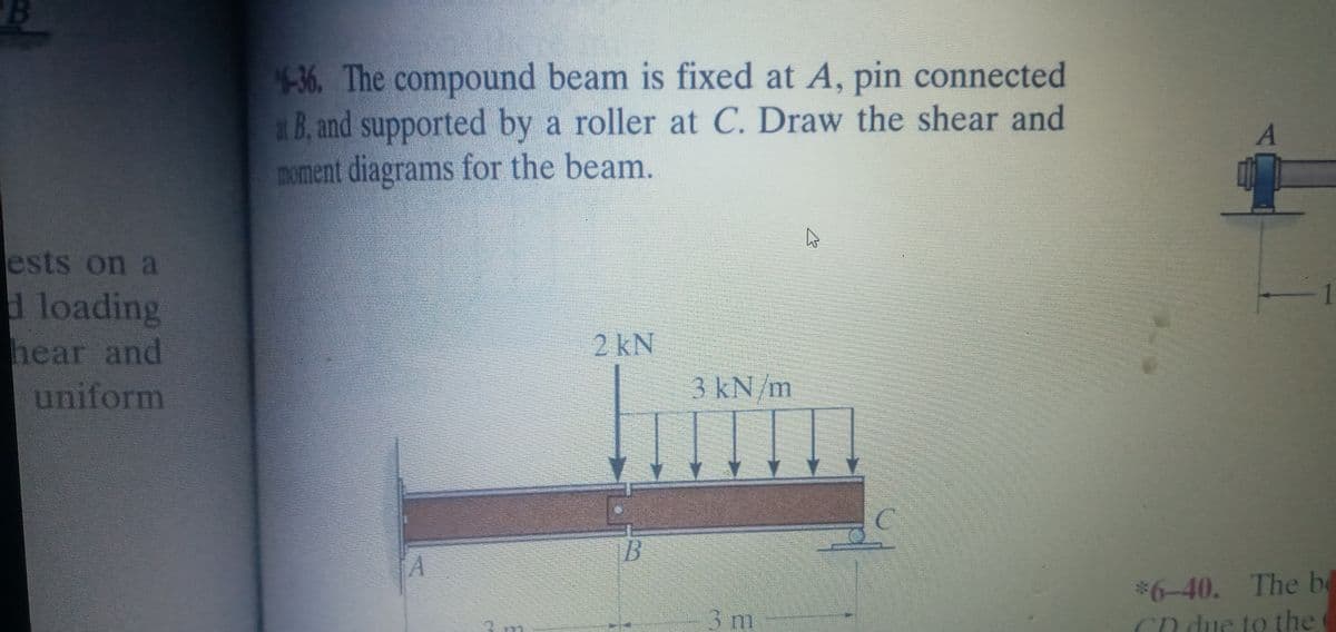
Transcribed Image Text:4-36. The compound beam is fixed at A, pin connected
x B, and supported by a roller at C. Draw the shear and
moment diagrams for the beam.
ests on a
1
d loading
hear and
uniform
2 kN
3kN/m
C.
B
$6-40. The be
Cn due to the
3 m
Expert Solution
This question has been solved!
Explore an expertly crafted, step-by-step solution for a thorough understanding of key concepts.

This is a popular solution!

Trending now
This is a popular solution!

Step by step
Solved in 7 steps with 4 images

Recommended textbooks for you
Mechanics of Materials (MindTap Course List)
Mechanical Engineering
ISBN:
9781337093347
Author:
Barry J. Goodno, James M. Gere
Publisher:
Cengage Learning
Mechanics of Materials (MindTap Course List)
Mechanical Engineering
ISBN:
9781337093347
Author:
Barry J. Goodno, James M. Gere
Publisher:
Cengage Learning