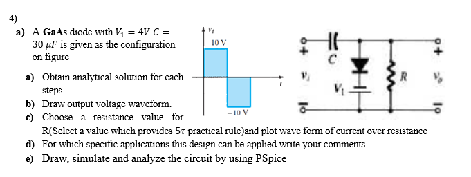
a) A GaAs diode with V₁ = 4V C = 30 µF is given as the configuration on figure a) Obtain analytical solution for each steps b) Draw output voltage waveform. c) Choose a resistance value for Vi 10 V V₂ R -10 V R(Select a value which provides 57 practical rule)and plot wave form of current over resistance d) For which specific applications this design can be applied write your comments e) Draw, simulate and analyze the circuit by using PSpice
a) A GaAs diode with V₁ = 4V C = 30 µF is given as the configuration on figure a) Obtain analytical solution for each steps b) Draw output voltage waveform. c) Choose a resistance value for Vi 10 V V₂ R -10 V R(Select a value which provides 57 practical rule)and plot wave form of current over resistance d) For which specific applications this design can be applied write your comments e) Draw, simulate and analyze the circuit by using PSpice
Oh no! Our experts couldn't answer your question.
Don't worry! We won't leave you hanging. Plus, we're giving you back one question for the inconvenience.
Submit your question and receive a step-by-step explanation from our experts in as fast as 30 minutes.
You have no more questions left.
Message from our expert:
Your software-based Pspice simulation question does not match the subject you selected. Please ask a question in one of the 30+ subjects available. We've credited a question to your account.
Your Question:
Hello I hope you are doing well, this question has been answered many times on bartleby, please don't copy, I want a new solution and more clarification of the solution, use the keyboard, don't use handwriting please
Transcribed Image Text:a) A GaAs diode with V₁ = 4V C =
30 µF is given as the configuration
on figure
a) Obtain analytical solution for each
steps
b) Draw output voltage waveform.
c) Choose a resistance value for
Vi
10 V
V₂
R
-10 V
R(Select a value which provides 57 practical rule)and plot wave form of current over resistance
d) For which specific applications this design can be applied write your comments
e) Draw, simulate and analyze the circuit by using PSpice

Knowledge Booster


Learn more about
Need a deep-dive on the concept behind this application? Look no further. Learn more about this topic, electrical-engineering and related others by exploring similar questions and additional content below.Recommended textbooks for you

Introductory Circuit Analysis (13th Edition)
Electrical Engineering
ISBN:
9780133923605
Author:
Robert L. Boylestad
Publisher:
PEARSON

Delmar's Standard Textbook Of Electricity
Electrical Engineering
ISBN:
9781337900348
Author:
Stephen L. Herman
Publisher:
Cengage Learning

Programmable Logic Controllers
Electrical Engineering
ISBN:
9780073373843
Author:
Frank D. Petruzella
Publisher:
McGraw-Hill Education
Introductory Circuit Analysis (13th Edition)
Electrical Engineering
ISBN:
9780133923605
Author:
Robert L. Boylestad
Publisher:
PEARSON
Delmar's Standard Textbook Of Electricity
Electrical Engineering
ISBN:
9781337900348
Author:
Stephen L. Herman
Publisher:
Cengage Learning
Programmable Logic Controllers
Electrical Engineering
ISBN:
9780073373843
Author:
Frank D. Petruzella
Publisher:
McGraw-Hill Education

Fundamentals of Electric Circuits
Electrical Engineering
ISBN:
9780078028229
Author:
Charles K Alexander, Matthew Sadiku
Publisher:
McGraw-Hill Education

Electric Circuits. (11th Edition)
Electrical Engineering
ISBN:
9780134746968
Author:
James W. Nilsson, Susan Riedel
Publisher:
PEARSON

Engineering Electromagnetics
Electrical Engineering
ISBN:
9780078028151
Author:
Hayt, William H. (william Hart), Jr, BUCK, John A.
Publisher:
Mcgraw-hill Education,