4-The pinchoff voltage has the same magnitude as the a-Gate voltage b-Drain-source voltage c-Gate- source voltage d-Gate-source cutoff voltage
4-The pinchoff voltage has the same magnitude as the a-Gate voltage b-Drain-source voltage c-Gate- source voltage d-Gate-source cutoff voltage

Delmar's Standard Textbook Of Electricity
7th Edition
ISBN:9781337900348
Author:Stephen L. Herman
Publisher:Stephen L. Herman
Chapter18: Resistive-inductive Parallel Circuits
Section: Chapter Questions
Problem 13PP: In an R-L parallel circuit, IT=1.25 amps, R=1.2k, and XL=1k. Find IR

Related questions
Question
Choose the correct items of the following statements.
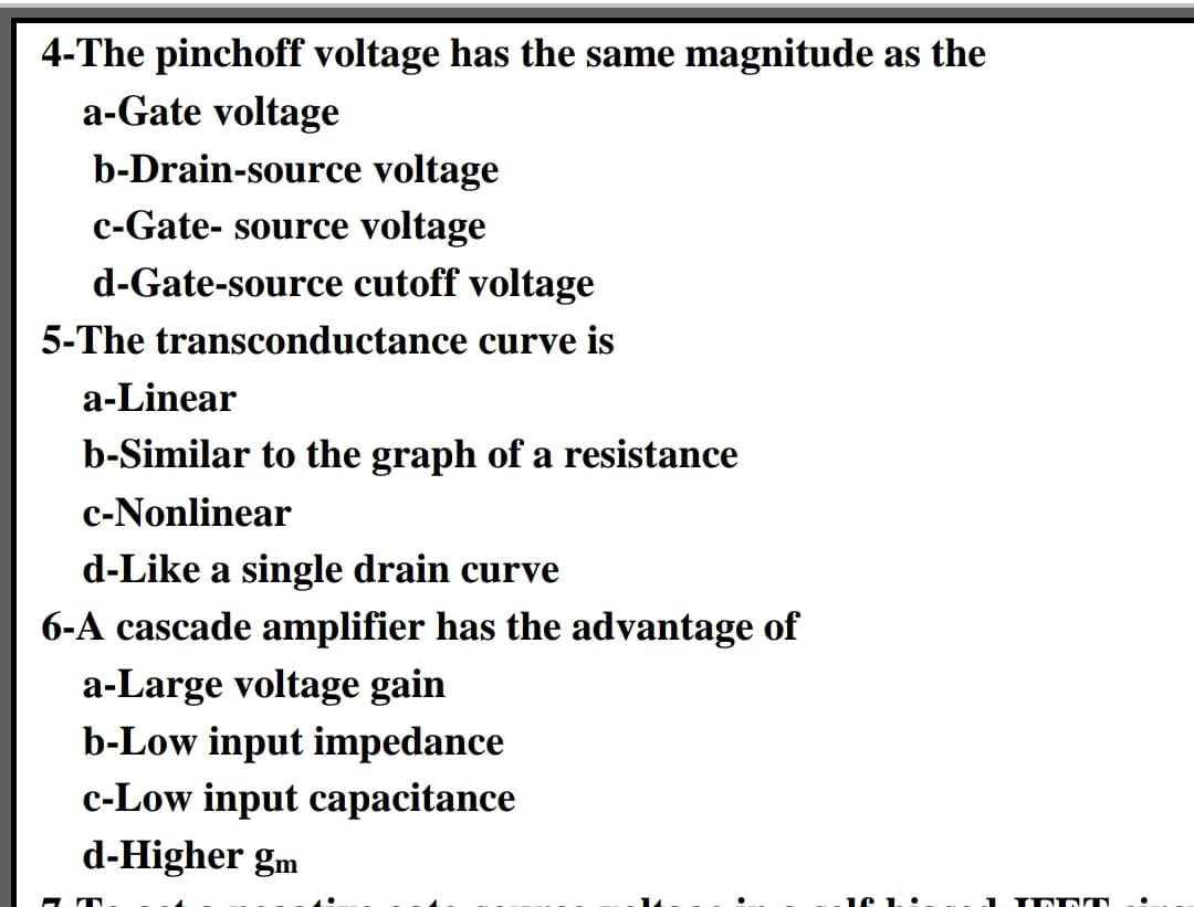
Transcribed Image Text:4-The pinchoff voltage has the same magnitude as the
a-Gate voltage
b-Drain-source voltage
c-Gate- source voltage
d-Gate-source cutoff voltage
5-The transconductance curve is
a-Linear
b-Similar to the graph of a resistance
c-Nonlinear
d-Like a single drain curve
6-A cascade amplifier has the advantage of
a-Large voltage gain
b-Low input impedance
c-Low input capacitance
d-Higher gm
1 IN DIT
Expert Solution
This question has been solved!
Explore an expertly crafted, step-by-step solution for a thorough understanding of key concepts.

This is a popular solution!

Trending now
This is a popular solution!

Step by step
Solved in 2 steps with 1 images

Knowledge Booster


Learn more about
Need a deep-dive on the concept behind this application? Look no further. Learn more about this topic, electrical-engineering and related others by exploring similar questions and additional content below.Recommended textbooks for you
Delmar's Standard Textbook Of Electricity
Electrical Engineering
ISBN:
9781337900348
Author:
Stephen L. Herman
Publisher:
Cengage Learning
Delmar's Standard Textbook Of Electricity
Electrical Engineering
ISBN:
9781337900348
Author:
Stephen L. Herman
Publisher:
Cengage Learning