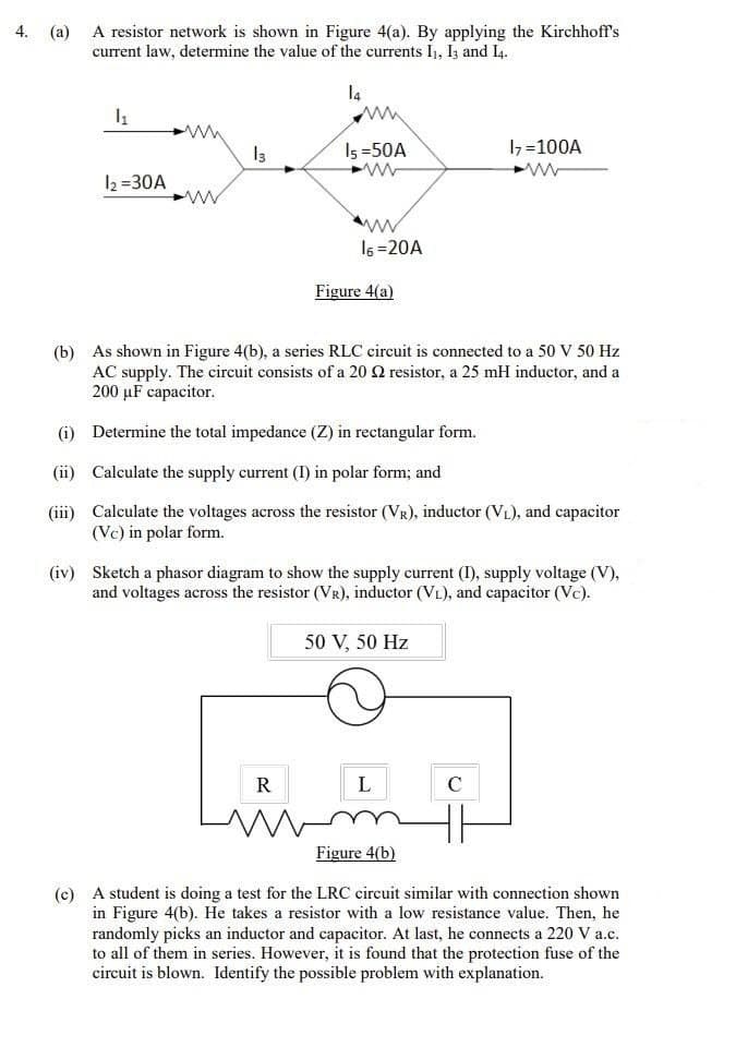
4. (a) A resistor network is shown in Figure 4(a). By applying the Kirchhoff's current law, determine the value of the currents I1, I3 and I4. l4 Is =50A 1=100A 12 =30A I6 =20A Figure 4(a)
4. (a) A resistor network is shown in Figure 4(a). By applying the Kirchhoff's current law, determine the value of the currents I1, I3 and I4. l4 Is =50A 1=100A 12 =30A I6 =20A Figure 4(a)

Power System Analysis and Design (MindTap Course List)
6th Edition
ISBN:9781305632134
Author:J. Duncan Glover, Thomas Overbye, Mulukutla S. Sarma
Publisher:J. Duncan Glover, Thomas Overbye, Mulukutla S. Sarma
Chapter2: Fundamentals
Section: Chapter Questions
Problem 2.17MCQ: Consider the load convention that is used for the RLC elements shown in Figure 2.2 of the text. A....

Related questions
Question
Transcribed Image Text:4. (a) A resistor network is shown in Figure 4(a). By applying the Kirchhoff's
current law, determine the value of the currents I, Iz and I4.
l4
Is =50A
I7=100A
I2 =30A
ww
16 =20A
Figure 4(a)
(b) As shown in Figure 4(b), a series RLC circuit is connected to a 50 V 50 Hz
AC supply. The circuit consists of a 20 resistor, a 25 mH inductor, and a
200 µF capacitor.
(i) Determine the total impedance (Z) in rectangular form.
(ii) Calculate the supply current (I) in polar form; and
(iii) Calculate the voltages across the resistor (VR), inductor (VL), and capacitor
(Vc) in polar form.
(iv) Sketch a phasor diagram to show the supply current (1), supply voltage (V),
and voltages across the resistor (VR), inductor (VL), and capacitor (Vc).
50 V, 50 Hz
R
L
C
Figure 4(b)
(c) A student is doing a test for the LRC circuit similar with connection shown
in Figure 4(b). He takes a resistor with a low resistance value. Then, he
randomly picks an inductor and capacitor. At last, he connects a 220 V a.c.
to all of them in series. However, it is found that the protection fuse of the
circuit is blown. Identify the possible problem with explanation.
Expert Solution
This question has been solved!
Explore an expertly crafted, step-by-step solution for a thorough understanding of key concepts.

Step by step
Solved in 2 steps with 2 images

Knowledge Booster


Learn more about
Need a deep-dive on the concept behind this application? Look no further. Learn more about this topic, electrical-engineering and related others by exploring similar questions and additional content below.Recommended textbooks for you
Power System Analysis and Design (MindTap Course …
Electrical Engineering
ISBN:
9781305632134
Author:
J. Duncan Glover, Thomas Overbye, Mulukutla S. Sarma
Publisher:
Cengage Learning
Power System Analysis and Design (MindTap Course …
Electrical Engineering
ISBN:
9781305632134
Author:
J. Duncan Glover, Thomas Overbye, Mulukutla S. Sarma
Publisher:
Cengage Learning