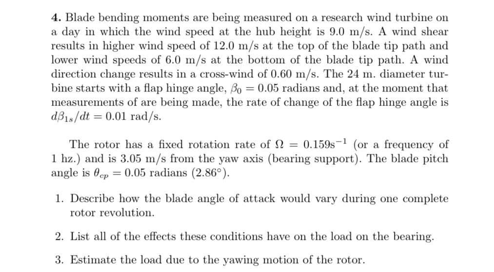
4. Blade bending moments are being measured on a research wind turbine on a day in which the wind speed at the hub height is 9.0 m/s. A wind shear results in higher wind speed of 12.0 m/s at the top of the blade tip path and lower wind speeds of 6.0 m/s at the bottom of the blade tip path. A wind direction change results in a cross-wind of 0.60 m/s. The 24 m. diameter tur- bine starts with a flap hinge angle, Bo = 0.05 radians and, at the moment that measurements of are being made, the rate of change of the flap hinge angle is %3D = 0.01 rad/s. %3D
4. Blade bending moments are being measured on a research wind turbine on a day in which the wind speed at the hub height is 9.0 m/s. A wind shear results in higher wind speed of 12.0 m/s at the top of the blade tip path and lower wind speeds of 6.0 m/s at the bottom of the blade tip path. A wind direction change results in a cross-wind of 0.60 m/s. The 24 m. diameter tur- bine starts with a flap hinge angle, Bo = 0.05 radians and, at the moment that measurements of are being made, the rate of change of the flap hinge angle is %3D = 0.01 rad/s. %3D
Principles of Heat Transfer (Activate Learning with these NEW titles from Engineering!)
8th Edition
ISBN:9781305387102
Author:Kreith, Frank; Manglik, Raj M.
Publisher:Kreith, Frank; Manglik, Raj M.
Chapter6: Forced Convection Over Exterior Surfaces
Section: Chapter Questions
Problem 6.34P
Related questions
Question

Transcribed Image Text:4. Blade bending moments are being measured on a research wind turbine on
a day in which the wind speed at the hub height is 9.0 m/s. A wind shear
results in higher wind speed of 12.0 m/s at the top of the blade tip path and
lower wind speeds of 6.0 m/s at the bottom of the blade tip path. A wind
direction change results in a cross-wind of 0.60 m/s. The 24 m. diameter tur-
bine starts with a flap hinge angle, Bo = 0.05 radians and, at the moment that
measurements of are being made, the rate of change of the flap hinge angle is
dB1s/dt = 0.01 rad/s.
%3D
The rotor has a fixed rotation rate of 2 = 0.159s-1 (or a frequency of
1 hz.) and is 3.05 m/s from the yaw axis (bearing support). The blade pitch
angle is 0ep
= 0.05 radians (2.86°).
1. Describe how the blade angle of attack would vary during one complete
rotor revolution.
2. List all of the effects these conditions have on the load on the bearing.
3. Estimate the load due to the yawing motion of the rotor.
Expert Solution
This question has been solved!
Explore an expertly crafted, step-by-step solution for a thorough understanding of key concepts.
Step by step
Solved in 4 steps with 3 images

Knowledge Booster
Learn more about
Need a deep-dive on the concept behind this application? Look no further. Learn more about this topic, mechanical-engineering and related others by exploring similar questions and additional content below.Recommended textbooks for you

Principles of Heat Transfer (Activate Learning wi…
Mechanical Engineering
ISBN:
9781305387102
Author:
Kreith, Frank; Manglik, Raj M.
Publisher:
Cengage Learning

Principles of Heat Transfer (Activate Learning wi…
Mechanical Engineering
ISBN:
9781305387102
Author:
Kreith, Frank; Manglik, Raj M.
Publisher:
Cengage Learning