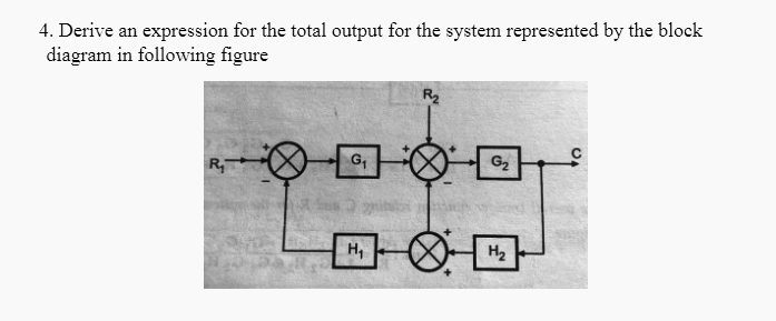
4. Derive an expression for the total output for the system represented by the block diagram in following figure R₂ G₁₂ R₁ H₁ H₂
Q: A single phase transformer of (k) transformation ratio is to be used as a step-up autotransformer.…
A: Given data : Transformation ratio = K KVA capacity is increased by 50%.
Q: What is the operating time of relay B for fault at F2 based on below figure? a) 0.6 sec 2.0 1.9 B A…
A: Relay is a circuit is used for protection of the device. It consists of single or multiple control…
Q: 1. A UK-based digital terrestrial television using DVB-Digital Video Broadcasting uses 16 QAM has a…
A:
Q: find the real power (P), reactive power (Q), and the apparent power (S) of the circuit given below
A:
Q: 8. An 8-bit ADC with a 10.0 V reference has an input of 3.637 V i. Determine the digital output. ii.…
A: Given, 8-bit ADC has Reference voltage (Vref) = 10.0 V Input voltage (Vi) = 3.637 V
Q: Determine the size of capacitor in uf necessary to increase the power factor to 0.90 if the load has…
A: (a) Given data, SL=200 KVA, VL=480 V, cosϕ1=0.70, Rline=0.03 Ω, f = 60 Hz Active power is given by,…
Q: Consult the plot of efficiency of solar cells prepared by the National Renewable Energy Laboratory…
A: According to the chart available of NREL, the highest efficiency cell is the three junction…
Q: Ulct the input signal frequencies fi and f
A:
Q: 1. Define Pitch Factor /Distribution Factor and present the formula to calculate. 2. Draw the
A: Since you have asked multiple questions, we will solve the first question for you. If you want any…
Q: 2. The load on a 250-V supply system is: 12 A at 0.8 power factor lagging; 10 A at 0.5 power factor…
A:
Q: Using a. What is the value of ra for Vas = -1V? b. What is the value of goat Vps = 10 V? (mA) 9 8 7…
A: Drain characteristic is drawn between drain current and VDS.
Q: B) Two transformers connected in open delta supply a 400-kVA balanced load operating at 0.866 p.f.…
A:
Q: True or False For a system function H(z) of an impulse response h[n], the DC gain |H(z)|z=1 = | Σ…
A: As per our guidelines we are supposed to be the first three questions only. Kindly repost the other…
Q: semicoductor has conductivity of 22.8 s/m, In C of 22.38, E₁ of 0.67 ev, k= 8.62 x 10⁵ ev /k…
A: Given data, The value of the conductivity (σ) is 22.8 s/m ln C = 22.38 , Ea = 0.67 ev , k =8.62×10⁻⁵…
Q: It is the amount of light incident on (striking) a surface. a. Illuminance b. None of the above c.…
A:
Q: Determine current I, in the circuit of 5/0° A 892 /10 22 m using mesh analysis. 492 -1292 -j252…
A: Given here a circuit and asked to find the current I0 . Given circuit is
Q: Determine R and Vz Given: ILMAX=200 micro ampere ILMIN=0 ampere V₁=12V V-16V R VL=12V
A: The Zener diode is used as a voltage regulator in the above circuit, where it cut-offs the supply to…
Q: Solve the given nonhomogeneous ODE (Show the details of your work.) Sketch or graph the solution.…
A: Dear student as per our guidelines we are supposed to solve only one question in which it should…
Q: A Germanium diode carries a current of 1 mA at room temperature when a forward bias of 0.15 V is…
A: Given: The current is 1 mA. The voltage is 0.15 V.
Q: FALSE O O TRUE O An employee at LaserKinetics.com borrows $10,000 on May 1 and must repay a total of…
A: Amount borrowed - $10000 Amount repayed after 1 year- $ 10800 Interest amount= amount repayed -…
Q: B) A three-phase, 50 Hz, A-Y connection. The line voltages of primary and secondary are 3300V and…
A:
Q: Given the characteristic equation of the denominator below, is the system: 25 G(s) = s² + 3s + 25 O…
A: Given: Gs=25s2+3s+25
Q: Score 5. Figure 2 represents for three sets of sequence components. (a) Fill in the brackets in…
A: As per Bartleby policy we can answer only one question at a time, so I am solving first question for…
Q: 1. What are the two ways of generating DSB_SC. 2. What are the applications of balanced modulator?…
A: Since you have asked multiple questions, we will solve the first question for you. If you want any…
Q: Determine the z parameters for the circuit shown in below. 6Ω 592 ww www + V₁ 0.66V 422 + V₂
A: Given Circuit:-
Q: Q4/ For the circuit in figure below, find i and in2 for the cases of supply voltage (VS) 20 V, 12 V,…
A: Given: VZ1=13VVZ2=7VAssume diode D3 is idealCondition for conduction od Zener diode is:VA>VZ1 ,…
Q: 1. To minimize the effect of the feedback circuit loading in oscillation frequency we we..........…
A: Since there are 4 different questions, as per the guidelines, in the following section, the first…
Q: K The open loop transfer function of a unity feedback system is given by G(s) s(1+57); where 'K' is…
A: Standard second order transfer function C(s) C(s)=ωn2s2+2ξ ωns+ωn2ξ= damping ratioωn= Natural…
Q: f. g. h. i. j. V = 50 V, I = 20 mA V = 45 V, I = 9 mA V = 10 V, I = 5 A V = 1 kV, I = 1mA V = 240 V,…
A:
Q: Which of the following statements is true for a series RLC circuit tuned at resonant frequency.
A: If we apply a variable frequency supply to the series RLC circuit, at particular frequency the…
Q: 4. How much is the percentage increase in bandwidth efficiency if a broadcast system shifts from 8…
A:
Q: Determine the transmission ABCD parameters I₁ 1 Ω 1 F mm 1 + V1 1 Ω 1F 12 + V2
A: For the above given question we need to calculate transmission parameters of the circuit.
Q: The unit-step response of a unity feedback system with open loop transfer function is shown in the…
A: Given a unity feedback open-loop transfer function, Gs=Ks+1s+2 Hs=1 Unit response, Rs=1s Curve:
Q: 8.a. What is the purpose of relay CRE in the roll stand machine? A. Relay CRE is used as an…
A: CRE relay is used to detect fault in the input circuit. It is used in stop button of contact welding…
Q: Design a bias network for a depletion-mode NMOS transistor to give a Q-point of (250 µA, 7.5 V) with…
A: Given data, VDD=15VVTN=-4VKn=1mA/V2ID=250μAVDS=7.5V
Q: Calculate the common emitter amplification factor of a transistor with a common base amplification…
A: For the above given question we need to calculate the value of common emitter amplification factor.
Q: НІНІНІНІНІ fv oooo K M -x(t) - f (t)
A:
Q: A bridge full-wave rectifier with forward resistance of 2 ohm supplies power to a 100 ohm load from…
A: Bridge full-wave rectifier: It has four diodes. Two diodes are working for each half-cycle period.…
Q: 5 milli-second. What voltage is induced across the secondary ?
A: When two coils are placed side by side and the current flows in the one coil has any change, it will…
Q: A-Prove that the efficiency of class-B power amplifier is n = VL(P)*78.53%. Vcc
A:
Q: Determine VCB in the transistor circuit shown. The transistor is of silicon and has B = 150 * Rc100…
A: Given, The transistor circuit, β=150
Q: What is the gain for OPAM in figure (a) and (b) when R₁= 2 kohm, R₁ 200 kohm. R₁ V (a) (b) www R₁ •…
A: Inverting Amplifier- An inverting amplifier takes the input through its inverting terminal through a…
Q: Q91 For the Logic Circuit shown in figure (6) write the SOP logical expression of the function (F)…
A:
Q: (1) List 3 characteristics of an ideal op-amp. (ii) Name 2 basic circuit applications for linear and…
A: NOTE- As per the rules we can answer only sub-parts from the first question part, please post the…
Q: Find the stability range for the unity feedback discrete control system with the open loop transfer…
A: We know that The general characteristic equation is 1+G(z)H(z) =0 Here given unity feedback…
Q: Compute the rms value of the voltage waveform shown in Fig. v(t) (V) 4 ил. 2 4 6 8 t(s)
A: By using the concept of signal and systems we need to calculate the value of RMS voltage of the…
Q: Calculate the DTFT ?(?^??) of the signal x[n] = {x[0]= 1, 1, 2}
A:
Q: A series type ohmmeter, designed to operate with a 9-V battery, the meter movement has an internal…
A: Given data : Battery Voltage Vb=9V Resistance R1=49kΩ Full scale deflection current ifsd=100μA…
Q: Two identical wave generators in a ripple tank produce an interference pattern using a wavelength of…
A: Given data, Wavelength (λ)=2.58cm n=1
Q: 1. Determine total capacitance looking at the terminals 'a' and 'b' of Figure 1. 94 16 14 18 12 16…
A:
Step by step
Solved in 3 steps with 3 images
- Which of the following is not a requirement for an electric circuit? a. a source b. a path c. a load d. a signal lightmaysons rule and reduction block diagramDiscrete Signals and Discrete Time systemsx[n1] = (values) 9 any random integer values from -10 to 5x[n2] = (values) 9 any random integer values from -5 to 5 a. Plot the graph setting the middle integer value at n = 0 showing the all samples.b. Plot the graph x[-n] showing all the samples.c. Plot the graph x[n-3] showing all the samples.d. Plot the graph x[n+2] showing all the samples.e. Plot the graph x[2n] showing all the samples.f. Plot the graph x[n/3] showing all the samples.g. Evaluate the convolution of x[n1] and x[n2].
- Identify the no. of positive numbers and zeros from the list of numbers. The length of the list is in ML 2200H and series itself begins from ML 2201H. Assume the sum to be greater than FFH. Store the results in ML 2300H and 2301H.Complete SolutionDraw the waveform of the given clipper circuit and determine the following: a.) At 0V, what is the output voltage?b.) At +20V, what is the output voltage?c.) At -5V, what is the output voltage?Write an expression for the output voltagein terms of the input voltage for the circuit. Diode D is formed from adiode-connected transistor, and all three transistors are identical
- Attampet with only two: 1: Prove that the dynamic resistance of diode is ra=26mv/Ip. 2:Prove that the ripple voltage of HWR is Viru=V+Vde and the ripple factor of HWR 121%, u=40.5%. 3: Using silicon diode design a clamper that will produce output V-20Sin wt+10 (v) when the input voltage is Vo=20Sin wt-10 (V).Draw the circuit diagram and the input and output signals. 4:The 6-V zener diode has a maximum rated power dissipated of 690 mw.Its reveres current must be at least 3mA to keep it in breakdown. Find a suitable value for Rs if V; can vary from 9v to 12v and Ri. can vary from 5000 to 1.2KO.I need all the values plsWhat is the advantage of using square wave-form as an Input Signal? What is the shape ofthe output when the input signals are sinusoidal and triangular in shape? ( Use Functiongenerator and Oscilloscope to observe the output)