4. Describe two steps that could be taken to reduce the likelihood of cavitation.
Q: 6000mm 6000mm X kN ww A Y kN www 6000mm В C
A:
Q: Solve for the angle at the hinge support and the deflection at point C. El= 20000KN-m2. Use…
A: Given, There is a simply supported beam given in the question.. The total length of the beam =…
Q: From the Beam shown: a) Write the Shear and Moment Equations. b) Draw the Shear and Moment Diagrams.…
A:
Q: Replace the loading by an equivalent resultant force and couple moment acting at point O. Suppose…
A: Equivalent resultant force Systems of equal force. The underlying principle is that two force…
Q: Write the equations of shear and moment as a function of x at segment between B and C if the origin…
A:
Q: Memo No. Date Mo Tu We Th Fr Sa Su P lialy sis by cs lpe Deflection metud) 5m 3 m 12
A: In given frame Data is insufficient for solving the problem
Q: 2- What are the procedures necessary to implement a wall foundation on liquid land?
A: Wall Foundation: Wall foundation is the masonry walls below the ground level. These are the main…
Q: Find the value of force if work done is 520 J and displacement is 42 m
A:
Q: Determine the maximum shearing stress(MPa) that can be developed in a solid steel shaft if it will…
A:
Q: 3 in. -3 in.- Problem #2 6 in. For Figure 2, a) Determine the moment of inertia of the area about…
A:
Q: An activated sludge tank is 30 m long 9 m wide and has liquid depth of 4 m. The influent sewage flow…
A: Given data- Dimensions of the activated sludge tank-L=30mB=9mD=4mInfluent sewage flow Qo=3.5…
Q: 1- A machine and its foundation weight 270 kN. The spring constant (for each spring) and the…
A:
Q: Determine the minimum width "b" of the beam shown if the flexural stress is not to exceed 13 MPa.…
A:
Q: 6- Draw the free-body diagram of each object.
A:
Q: The _________ of the combined footing must coincide with the resultant of its axial loads
A: Combined footing is used for two or more columns and serves as single footing.
Q: The length of curve at side of PC is 45 while on the PT is 5 having an elevation of 108.6 is found…
A:
Q: Density of concrete: 2400 kg/m?. No tail water. Foundation condition: Inferior condition with…
A: Hi! Thank you for the question As per the honor code, We’ll answer the first question since the…
Q: The line connecting PC to PT is equal to 123 m. If this line makes an angl with the back tangent of…
A:
Q: Using the method of sections, determine the force in members BD, DE and DF. D 1 m F 20 kN B 1 m A G…
A:
Q: 4. Find the lightest S-shape for the beam shown if the working stress in bending is 175 MPa. What is…
A: The given figure of beam is shown below:
Q: If a 24-in. steel pipe 8000 ft long is designed for a stress of 15,000 psi under a maximum static…
A: ####Increase in stress of pipe material ###
Q: 5 If g is the punching shear resistance per unit area a, is the side of a square footing for a…
A:
Q: F6-14.) Determine the horizontal and vertical components of reaction at pin C. 2.5 kN Referring to…
A: To Determine The horizontal and vertical components of reaction at pin C.
Q: 60 kN F 30 kN- 5 m 60 kN 30 kN -5 m -5 m -5 m -5 m -5 m
A: We need to find out the degree of static indeterminacy, Ds
Q: An open rectangular tank measuring 5 m long, 1.82 m wide, and 2 m high is filled to a depth of 1.6 m…
A:
Q: Calculate the dry unit weight of soil having void ratio of 0.73 and a value of Gs of 2.72. Take unit…
A:
Q: The line connecting PC to PT is equal to 150 m. If this line makes an angle of 15 with the back…
A:
Q: What will be the value of reduction factor R1 if value of At is given to be 500 ft2 ? (a) 0.5 (b)…
A: ASKED: To determine the value of reduction factor R1 for given value of tributary area. Given,…
Q: alent location on the beam measured from point A.
A: FInd the total load acting W=∫0Lw(x)dxW=∫0Lwo(sinπx2L)dxW=wo[-cosπx2Lπ2L]0LW=wo(2Lπ)so equivalent…
Q: Determine the cross sectional area of the given cross section notes: LEFTMOST LEFT CENTER RIGHT…
A:
Q: 6) Due to a fabrication error the inner circle of the tube is eccentric to the outer circle. By what…
A:
Q: Identify a primary or secondary pollutant that would likely be present at higher concentratios in…
A:
Q: Find Member GN, FB and DE
A: To Determine Internal force in members GB, FB and DE. Correction in question :- Instead of GN which…
Q: In a wide rectangular channel having a depth y = 1.8 m and unit width discharge q = 1.5 m²/s, an…
A: q = 1.5 m2/s b1 = 6m Q = q *b1 = 1.5*6 = 9m3/s
Q: Determine the coordinates of the centroid of the shaded area. y 15 E 30 35 15 40 50 I 30 - x 100…
A:
Q: 104 kips kips 66 0.25 kips/ft 25kips-ft A В C D 10' @ 3 span
A:
Q: Compute for the area of the cross section, considering b is 8.8 meters: 7.34 7.49 + 2.26 + 4.28 +…
A: To Determine Areas of the cross sections
Q: 3 kips/ft 85 k-ft AZ В 15' 15
A:
Q: Determine the height h above the base of the centroid of the cross-sectional area of the beam.…
A:
Q: Reservoir, 8,450 ft City A 8,250 ft 5,000 ft 24 in, 5,000 ft City B 8,200 ft 18 in. 36 in
A:
Q: Pipe L (m) Diameter (mm) f 1052 600 0.025 890 600 0.025 3 890 650 0.025 4 1055 650 0.025 2 25 m-
A:
Q: 134. Beam loaded as shown in Fig. P-434. Ans. 60 kN 20 kN/m M = 120 kN a
A:
Q: Given that J is no. of joints. B and R are no. of members and no. of reactions. If B= 4, R= 3 and J…
A:
Q: The radius of the first curve passing PC is equal to 220 m, while of the second reversed curve is…
A:
Q: Find degree of static indeterminacy
A: Given data : Number of member (m)=11 Number of Joint (J)=7 Support=Pinned and Roller support Number…
Q: A truss is subjected to different force combinations as shown in the figure below. The…
A: Here we need to find deformation in both the direction i.e. in x and y directions of point C. For…
Q: G 60 60° D 10 10' 20 10 10' 1200 lb 1200 lb 1200 ib 1200 ib Determine the internal force on: Member…
A: LAC = 40feet
Q: A cable weighing 40N per meter of length is suspended from point A and passes over a small…
A:
Q: A -6% grade is followed by a 2% grade intersecting at Sta. 15+750, with an elevation of 372.25 m.…
A:
Q: Compute for the area (m2) of fill, considering b is 8.9 meters: 9.81 8.67 + 4.54 - 6.81
A:
Do not answer the question about drawing a graph
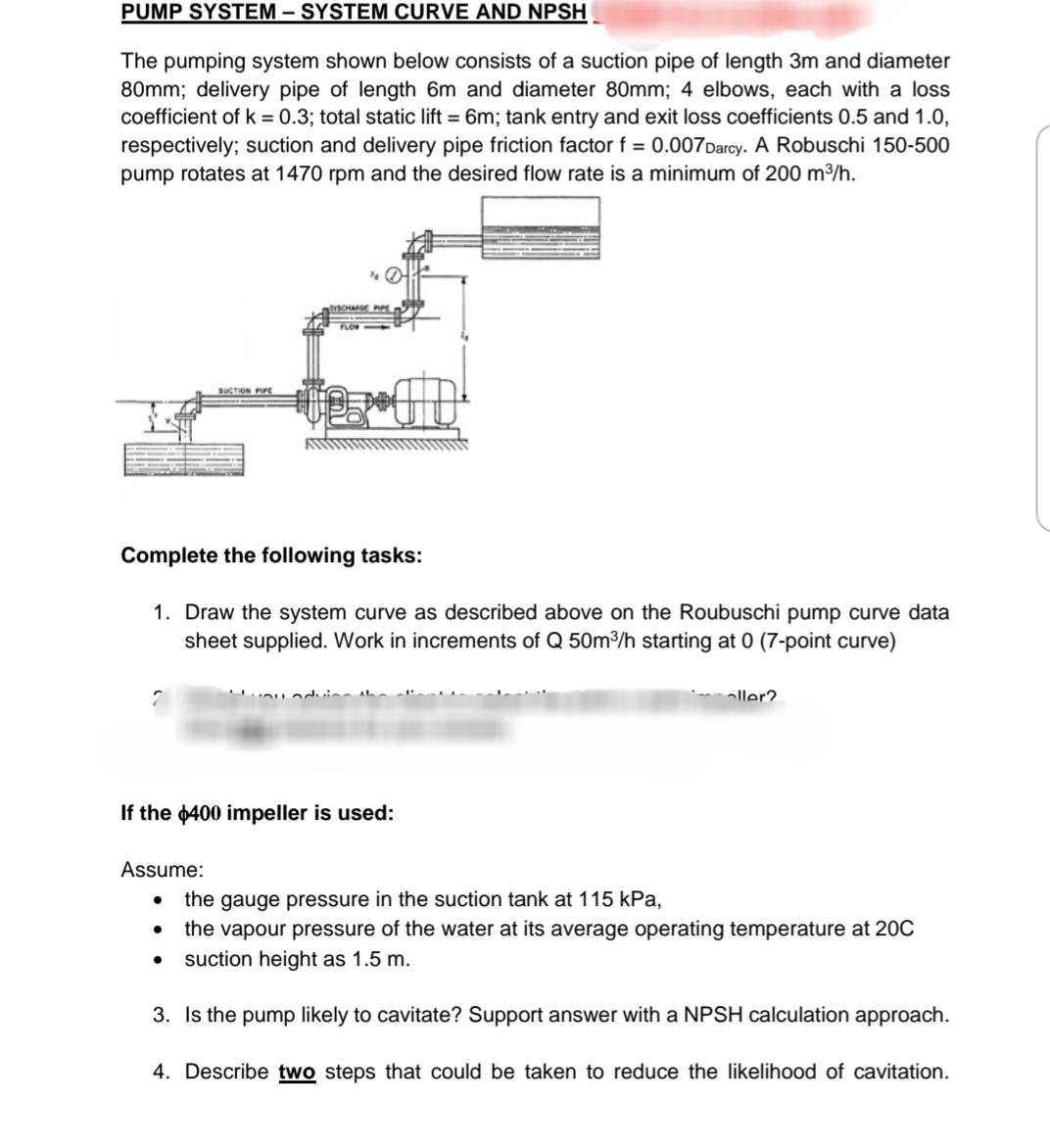
Step by step
Solved in 2 steps
- Plz, solve the parts of this question. Hydraulics. My Reg.No: 5395 Question # 02:a). The flow rate in a long rectangular channel (n = 0.014) is equal to the last three digits of your registration number in cubic feet per second. The channel is 12ft wide and there is an abrupt change in slope from 0.0019 to 0.018. PLOT a figure showing normal depths, critical depths and water surface profiles? b).Using Rayleigh’s procedure, PRODUCE an expression for the discharge over a spillway (Q) which is a function of head above spillway (H), height of spillway (h), velocity of flow (V) and acceleration due to gravity (g)?Two water pumps are arranged in series. The performance data for both pumps follow the parabolic curve fit Havailable = H0 − aV.2 . For pump 1, H0 = 6.33 m and coefficient a = 0.0633 m/(Lpm)2 ; for pump 2, H0 = 9.25 m and coefficient a = 0.0472 m/(Lpm)2 . In either case, the units of net pump head H are m, and the units of capacity V. are Lpm. Calculate the combined shutoff head and free delivery of the two pumps working together in series. At what volume flow rate should pump 1 be shut off and bypassed? Explain.Two reservoirs are connected by a pipeline consisting of pipe 1, pipe 2, pipe 3connected in series with length of 170 m, 300 m, 210 m respectively. Thedifferent in water surface levels in two reservoirs is 12 m. The friction coefficientfor pipe 1, pipe 2 and pipe 3 are 0.0052, 0.005 and 0.0048 respectively. Based onTable 2 and the setting given, determine the flowrate of the flow if the entranceloss coefficient is 0.25 considering :(i) minor losses; and(ii) neglecting minor losses pipe 1 =230(mm) Pipe 2 =330(mm) Pipe 3 = 430(mm)
- A pump draws water (SG=0.998) from reservoir A and transport it to reservoir B, with the static Suctionhead 8m and static discharge head of 28 m. The diameter of the suction pipe is 15.24 cm, and the diameter of the discharge pipe is 4 in. The total head loss from A to B is 25% of TDH, and the head loss at the discharge line is 90% of the total headloss. If the pump capacity is 60 Ips, determine the following:a. Pump Break power if the efficiency is 82% b. Reading of the pressure gauge installed at the suction flange of the pump C. Reading of the pressure gauge installed at the discharge flange of the pumpTwo reservoirs are connected as shown in the figure. The difference in Elevation of the two reservoirs is 6.88m. Darcy-Weisbach friction factor for all pipes, f=0.0238. Pipe 1: Length=3500m Diameter=70cm Pipe 2 and 3: Length=1750m Diameter=35cm Compute the discharge in the pipe one in L/s. Compute the discharge in the pipe three in L/s.1. Compute the head loss in a pipe with diameter 300 mm for a length of 15,000 meters and carrying a flow of 0.097, if f=0.02. (Hint: Use h=(0.0826fL(Q^2))/(D^5)
- If the total flow of 4.0m3/? takes place in the three pipes. Determine the distribution offlow. The pipe lengths, diameters and frictions factors are shown below.Operating conditionsDetermine the operating conditions (HP, Q, ep, and Pi) of a pump capable of moving water (68°F) from reservoir A (water surface elevation = 102 ft) to reservoir B (water surface elevation = 180 ft). The 12” diameter pipe connecting the two reservoirs has a length of 8700 ft. The pump characteristics are given in the graph; plot the system curve on this graph and include with your solution. To calculate friction loss, assume fully turbulent conditions with e = 0.006 ft, and include minor losses for a square-edged entrance and submerged exit. Also verify that the pump efficiency obtained from the pump characteristic curves corresponds with the pump efficiency obtained from the power equation (? =????; note that 1 HP = 550 ft-lb/s). Then repeat the calculations for 50 years from now when e has increased to 0.04 ft. Plot the new system curve on the graph and verify the new efficiency.In the pipeline shown in the figure, the diameter of all pipes (D) is 200 mm and their friction coefficient (f) is 0.02. Thisfor pipeline a) Calculate the maximum flow and draw the hydraulic slope plot. b) Flow rate Q=0.05 m3 To reduce to /s, calculate the required head loss on the valve and calculate the hydraulic slope line.draw. c) HP = 15 – 2000Q2 (Q:m3 /s, Hp: m) placement of a pump with characteristic equation at point BCalculate the flow rate and draw the hydraulic gradient line. Note: The criteria for 3 m < P/γ < 80 m and 0.5 m/s < V < 2 m/s along the pipeline must be met for all cases.
- Determine the flow in L/s into or out of each reservoir in the pipe system shown; use n=0.011 for all pipesWater is siphoned from the tank as shown in the figure below. the length of the pipe is 12 m and has roughness ratio (E/D=0.001) a) determine the flow rate and the pressure at point A, stagnation point, neglecting all loses. b) determine the flow rate and pressure at point A, stagnation point, assuming only the major loses are important c) determine the flow rate and pressure at point A, stagnation point, assuming all loses (minor and major) are important.*hydraulics *use handwritten A trapezoidal flume of most efficient proportion has a base of 1.5 m. Its full discharge is 3 m^3/s, If the same material is used for a most efficient rectangular section, Compute the decrease in the discharge. Choices: A. 0.44 m3/s B. 0:54 m3/s C. 0.64 m3/s D. 0.74 m3/s