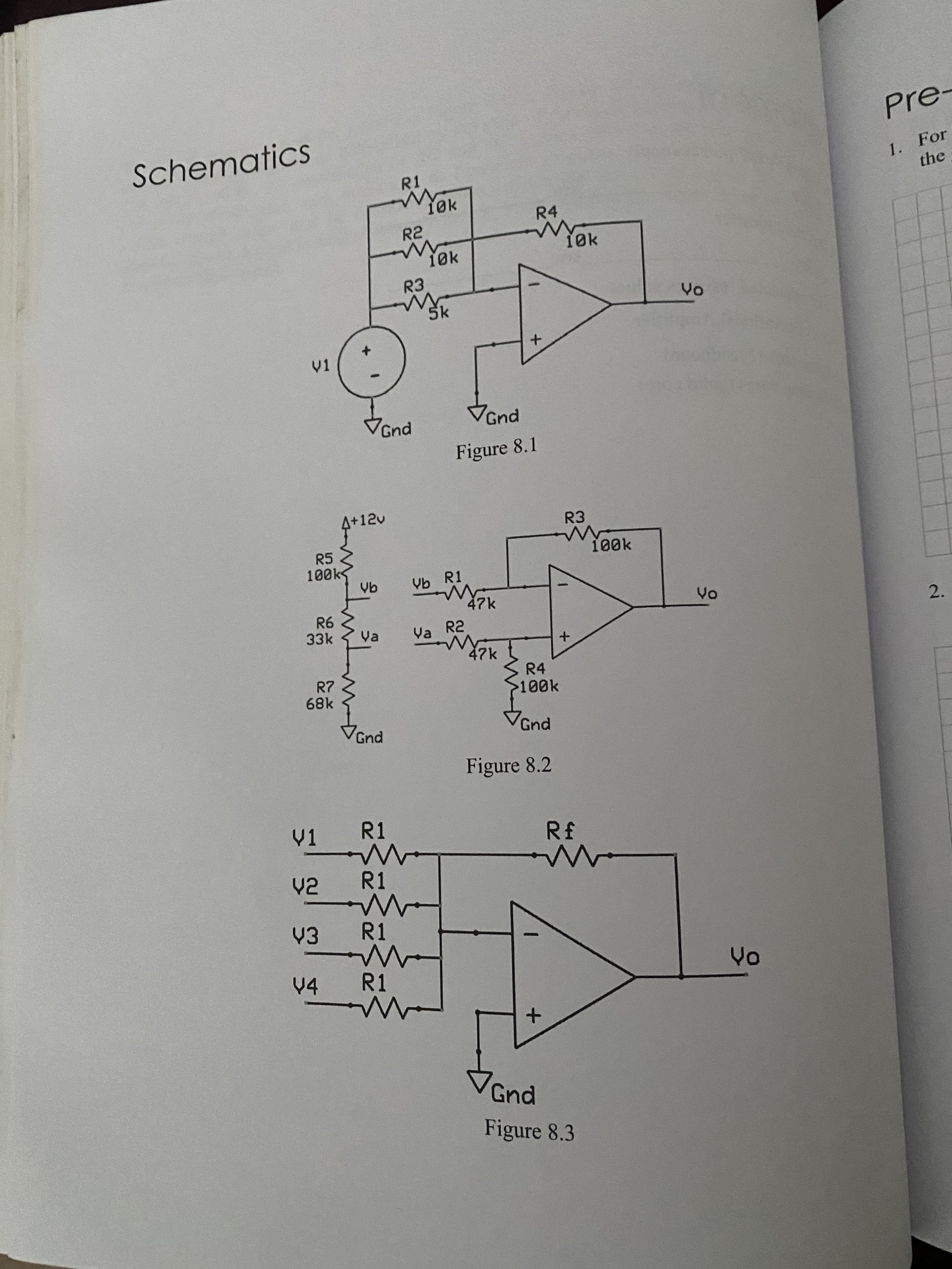
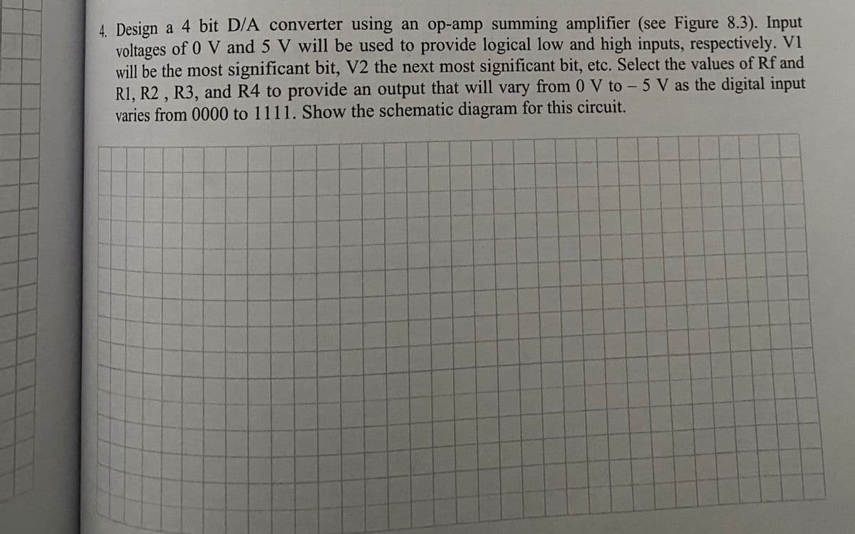
4. Design a 4 bit D/A converter using an op-amp summing amplifier (see Figure 8.3). Input voltages of 0 V and 5 V will be used to provide logical low and high inputs, respectively. V1 will be the most significant bit, V2 the next most significant bit, etc. Select the values of Rf and R1, R2 , R3, and R4 to provide an output that will vary from 0 V to - 5 V as the digital input varies from 0000 to 1111. Show the schematic diagram for this circuit.
4. Design a 4 bit D/A converter using an op-amp summing amplifier (see Figure 8.3). Input voltages of 0 V and 5 V will be used to provide logical low and high inputs, respectively. V1 will be the most significant bit, V2 the next most significant bit, etc. Select the values of Rf and R1, R2 , R3, and R4 to provide an output that will vary from 0 V to - 5 V as the digital input varies from 0000 to 1111. Show the schematic diagram for this circuit.

Introductory Circuit Analysis (13th Edition)
13th Edition
ISBN:9780133923605
Author:Robert L. Boylestad
Publisher:Robert L. Boylestad
Chapter1: Introduction
Section: Chapter Questions
Problem 1P: Visit your local library (at school or home) and describe the extent to which it provides literature...

Related questions

Question
Transcribed Image Text:2.
Pre-
Schematics
1. For
the
R1
1øk
R4
R2
10k
V1
Gnd
VGnd
Figure 8.1
4+12v
R3
R5
Vb R1
47k
33k
Va
Va R2
R7
68k
R4
100k
Gnd
Gnd
Figure 8.2
V1
R1
于8
R1
R1
V4
R1
Gnd
Figure 8.3
Transcribed Image Text:4. Design a 4 bit D/A converter using an op-amp summing amplifier (see Figure 8.3). Input
voltages of 0 V and 5 V will be used to provide logical low and high inputs, respectively. V1
will be the most significant bit, V2 the next most significant bit, etc. Select the values of Rf and
R1, R2 , R3, and R4 to provide an output that will vary from 0 V to - 5 V as the digital input
varies from 0000 to 1111. Show the schematic diagram for this circuit.
Expert Solution
This question has been solved!
Explore an expertly crafted, step-by-step solution for a thorough understanding of key concepts.

Step by step
Solved in 3 steps with 3 images

Knowledge Booster


Learn more about
Need a deep-dive on the concept behind this application? Look no further. Learn more about this topic, electrical-engineering and related others by exploring similar questions and additional content below.Recommended textbooks for you
Introductory Circuit Analysis (13th Edition)
Electrical Engineering
ISBN:
9780133923605
Author:
Robert L. Boylestad
Publisher:
PEARSON

Delmar's Standard Textbook Of Electricity
Electrical Engineering
ISBN:
9781337900348
Author:
Stephen L. Herman
Publisher:
Cengage Learning

Programmable Logic Controllers
Electrical Engineering
ISBN:
9780073373843
Author:
Frank D. Petruzella
Publisher:
McGraw-Hill Education
Introductory Circuit Analysis (13th Edition)
Electrical Engineering
ISBN:
9780133923605
Author:
Robert L. Boylestad
Publisher:
PEARSON
Delmar's Standard Textbook Of Electricity
Electrical Engineering
ISBN:
9781337900348
Author:
Stephen L. Herman
Publisher:
Cengage Learning
Programmable Logic Controllers
Electrical Engineering
ISBN:
9780073373843
Author:
Frank D. Petruzella
Publisher:
McGraw-Hill Education

Fundamentals of Electric Circuits
Electrical Engineering
ISBN:
9780078028229
Author:
Charles K Alexander, Matthew Sadiku
Publisher:
McGraw-Hill Education

Electric Circuits. (11th Edition)
Electrical Engineering
ISBN:
9780134746968
Author:
James W. Nilsson, Susan Riedel
Publisher:
PEARSON

Engineering Electromagnetics
Electrical Engineering
ISBN:
9780078028151
Author:
Hayt, William H. (william Hart), Jr, BUCK, John A.
Publisher:
Mcgraw-hill Education,