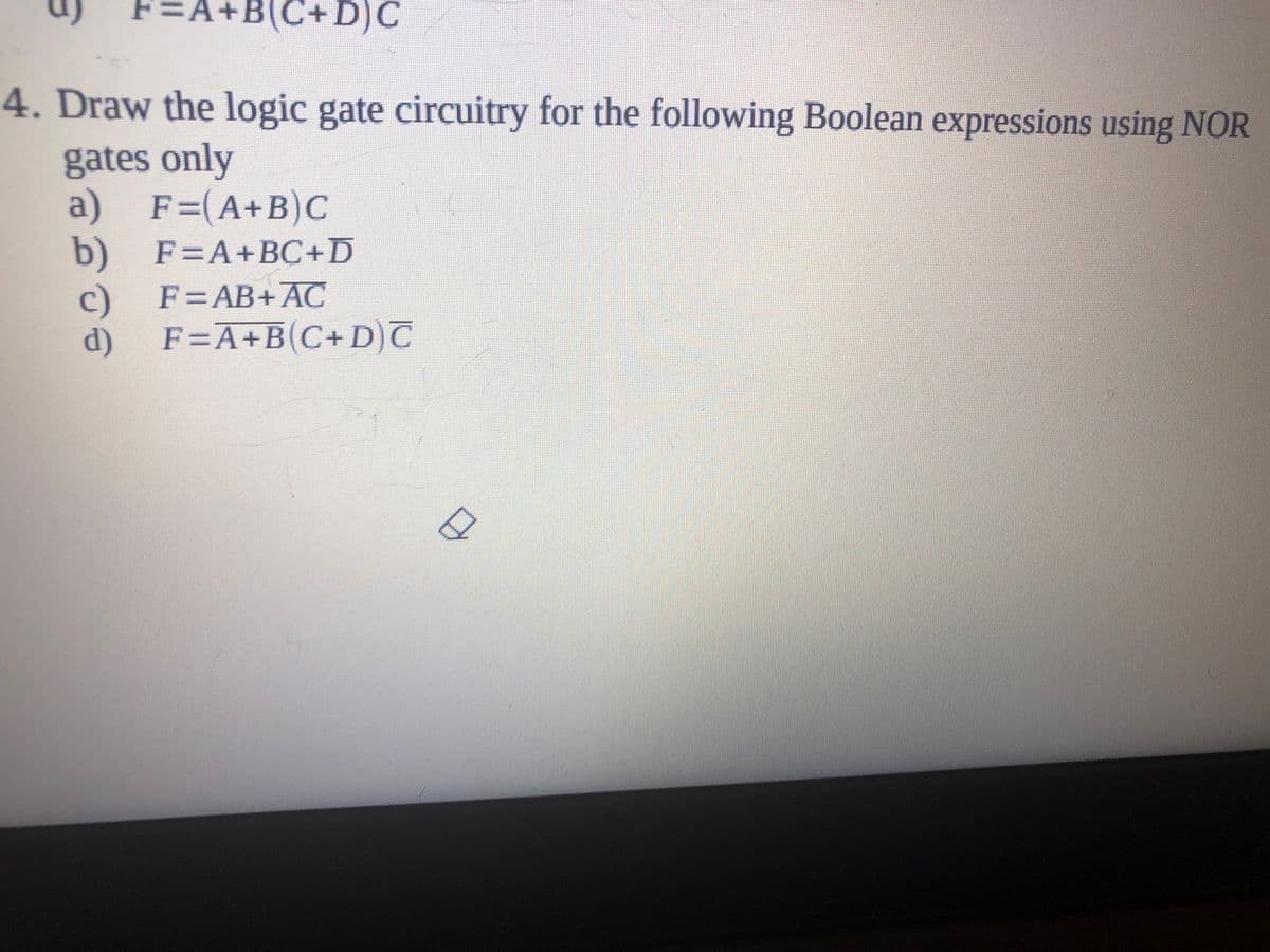
4. Draw the logic gate circuitry for the following Boolean expressions using NOR gates only a) F=(A+B)C b) F=A+BC+D c) F=A+B(C+D)T F=AB+AC d)


Q: Construct the logic circuits for the following Boolean expressions a. D= Ā(BC + D + C) + A b. C = (A…
A:
Q: С. Figure Q1 (c) shows a logic circuit with four inputs A, B, C, D and one output Y. Redraw the…
A: In the given circuit we have Not gate, AND gate, OR gate used. you can use NAND gate as follows:
Q: A combinational logic circuit has three inputs with sequence A, B, and C and two outputs with…
A: 1. Boolean Algebra – This forms the algebraic expression showing the operation of the logic circuit…
Q: Q4: Explain the following logic gates along with their truth table and symbols. a) OR b) AND c) NAND…
A: The logic gates: a) OR The OR gate is a digital logic gate that performs logical conjunction based…
Q: A combinational logic circuit is defined by the following three Boolean functions F = A +C + ABC F2…
A: Given : F1 = (A + C)' + ABC F2 = (A + C)' + A'BC F3 = AB'C + (A + C)' Implement the above three…
Q: Write Boolean Function for the following Logic circuit. OM The Boolean function for above logic…
A: Connecting the output of one logic gate to the input of another logic gate is how Boolean functions…
Q: NAND
A: NAND Gate: A logic gate is an electronic circuit that includes numerous input signals and a single…
Q: Create a 1-bit XOR circuit using only AND, OR, and NOT gates. Explicitly show all steps starting…
A: here truth table with logical expression and circuit diagram is stated in step 2.
Q: Construct a combinatorial circuit using inverters, OR gates, and AND gates that produces the…
A: we have to construct an combinational circuit using OR gates & AND gates that produced desired…
Q: QUESTION 2 What is the number of gates needed to create the logic circuit for the following boolean…
A: LOGIC CIRCUIT: Logic circuits are basically the basic building blocks of the general digital…
Q: A'- B DI -D- B' The Boolean expression for the above logic circuit is O a. F = (A' + B) + (B' +C) O…
A: It is based on computer architecture.
Q: Convert the following logic gate circuit into a Boolean expression. Write Boolean subexpression next…
A: This Question is from logic gates of computer architecture. A circuit diagram is given here and we…
Q: Draw logic diagrams of the circuits that implement the original and simplified expressions…
A: Draw logic diagrams of the circuits that implement the original and simplified expressions…
Q: Construct logic circuit diagram for the Boolean expression :A’.B+(A’.B’).(BC+B’.C’) by using NAND…
A: Let us first simplify the given boolean expression- A’.B+(A’.B’).(BC+B’.C’) =A'B+A'B'BC+A'B'B'C'…
Q: Draw the logic circuit of the full adder circuit block. the circuit that will perform the operation…
A: Draw the logic circuit of the full adder circuit block. the circuit that will perform the operation…
Q: Draw the non-abbreviated logic diagram for the following Boolean expressions. (You may use XOR…
A: K) (abc’) + (a’ b’ c’)’ Logic gate diagram is shown below - where K is output and a,b and c are…
Q: Create 2 logic diagrams with at least 4 inputs using at least 3 logic gates and provide their…
A: Two logic diagrams along with their truth table is given below.
Q: Create a non-abbreviated logic diagram for the following Boolean Expressions. You can use all gates.…
A: To create the non abbreviated logic diagram of Boolean expression a’b+ab’ first of all , you need…
Q: Given X is the standard SOP expression of a combinational logic circuit. X = A BC + A BC+ A BC+ ABC+…
A: Steps: Find missing terms. Convert them to expression.(1 is considered 0 here and vice versa) Write…
Q: Convert the following logic gate circuit into a Boolean expression. Write Boolean subexpression next…
A:
Q: 8. Draw a logic symbol diagram showing how you would connect only 2-input NAND gates to produce a…
A: 4 input OR gate: A+B+C+D By simplifying: A+B+C+D = (A+B) + (C+D) = (A'.B')' + (C'.D')'…
Q: A combinational logic circuit has three inputs equence A, B, and C and two outputs with seque d Y.…
A:
Q: Create a Truth Table and draw the logic circuit for (p ∨¬r) ∧ (¬p ∨ (q ∨¬r)).
A: A truth table is a logical table that determines whether or not a compound assertion is true.…
Q: Design a logic circuit that divides the clock frequency by two
A: Although it may seem simple to say so, we can't count except we have some kind of memory. The…
Q: Create a non-abbreviated logic diagram for the following Boolean Expressions. You can use all gates.…
A: Logic diagram of expression (a XOR b + b’ XOR c’) is given below,
Q: V. Problem Šolving: 1. Find the truth table for the logic circuit shown below. Авс F 0 0 0 0 0 1 0 1…
A: The gates that are shown in the diagram are said to be XOR gates These gates take 2 bits as inputs…
Q: Question (20): Draw a logic diagram using only two-input NOR gates to implement the following…
A:
Q: Logic Circuit using C++. A, B, C, and D are th
A: Implement the following Logic Circuit using C++. A, B, C, and D are the input bits while F is the…
Q: Use Boolean algebra to simplify the following expression, then draw a logic gate circuit for the…
A: check the step 2 for solution
Q: A combinational logic circuit is defined by the following two functions: F1 = ABD + ABC D+ BCD F2 =…
A: A combinational circuit is a circuit where we use different gates like decoder, encoder,…
Q: Redraw the logic diagram using 2-input basic gates only. BD DD ED Dro i Malays
A: Digital logic gates have more than one input, for example A, B, C, D, etc., but usually have only…
Q: Example:- Write the logic expression for the output function Y for the circuit shown in Figure. And…
A:
Q: Draw the circuits according to expressions using basic logic gate( 3 variables) Draw the circuits…
A: The logic circuits of the given expression F1
Q: The output of the logic circuit is ... A exnor B A exor B A or B A and B
A: Go through truth table. The final output is similar with xor gate .
Q: 1- A combinational circuit is defined by the following three functions: F1= XY+XYZ F2= XY + XYZ F3=…
A: 1- A combinational circuit is defined by the following three functions: F1= 2 + XYZ F2= X? + feYZ…
Q: Q: A combinational logic circuit has three inputs with sequence A, B, and C and two outputs with…
A: We need to draw the asm chart for the given circuit.
Q: build a two-level logic circuit, (consisting of different gates) and find the following: The truth…
A: A two-level logic circuit means irrespective of the number of logic gates (AND, OR, NOT, NAND, etc.)…
Q: construct the logic diagram using full adder/s W X Y Z CLC F = 0 if (X+Y) > (C+D) otherwise F = 1 F
A: Below is the answer to above question. I hope this will be helpful for you..
Q: Design a combinational logic circuit that Subtract (B8 B7 B6 B5 B4 B3 B2 B1) from (A8 A7 A6 A5 A4 A3…
A: The answer for the given question is as follows.
Q: 13. The output function 'f of the given logic circuit is 1 b A Io B->I1 C- I, Decoder 5 0- 3. 3 x 8…
A: Your answer is here
Q: Create a non-abbreviated logic diagram for the following Boolean Expressions. You can use all gates.…
A: Answer: Non-abbreviated logic diagram for the Boolean expressions: 1. a’b + ab’
Q: for this boolean expression X(YZ'+Y'Z) draw the logic circuit.
A: logic circuit for this boolean expression is given below
Q: Use Boolean algebra to simplify the following expression, then draw a logic gate circuit for the…
A:
Q: 1. Draw a single logic symbol for each circuit you set up in this experiment: a. 2-input NAND gate…
A: a) 2- input NAND gate b) 2- input NOR gate c) 2- input OR gate d) 2- input…
Q: Draw a logic circuit that performed by this logic expression: Ā·(B + C) · D ·E = Y
A:
Q: A combinational logic circuit has an output F=bc'd+a'c'd'+acd+a'b'c. To
A: ab'd should be the right answer that can remove the static hazard as for solving combinational logic…
Q: Given the truth table as in Table Q3, draw the simplified logic circuit using K-Map. b) Table Q3…
A: k-map: The k-map was intoduced Maurice Karnaugh in 1953 .The k-map stands for karnaugh map.The…
Q: The boolean expression for the below logic circuit is equivalent to * A B C (AB) C' A'C+B'C+AB A…
A: The gates given in logical circuit are: NAND gate XOR gate XNOR gate
Q: The output of a combinational logic circuit is F=A'D'+(A+B) (B'+C'). To remove the static one hazard…
A: The question is to choose the correct option from the given four options.

Step by step
Solved in 3 steps with 4 images

- Design a combinational logic circuit that takes a 3–bit input and has one output P. The P output should be active high only when the inputs corresponds to a prime number Note: the prime numbers: Prime numbers are 2, 3, 5, 7… Select one: a. P= AC+B b. P= A'C+A'B c. P= AC+A'B d. P= AC+A'B'Draw the non-abbreviated logic diagram for the following Boolean expressions. (You may use XOR gates.) A) ((a’)’)’C) a’b + ab’F) ((ab XOR b’) + a’b)’K) (abc’) + (a’ b’ c’)’N) (((a + b)’ + c)’ + d)’Given a 4-bit signed integer, design a circuit that outputs its absolute value. You can assume that the input will always have a valid output. (a) Draw a logic diagram of this circuit. You may use 4-bit half adder(s), 2x1 4-bit multiplexer(s), and any logic gate(s) in your design. (b) With the following Verilog code, implement your design above in Verilog. module half_adder (input [3:0] a, input [3:0] b, output [3:0] s); assign s = a + b; endmodule module mux(input [3:0] D0, input [3:0] D1, input S, output reg [3:0] O); always @(*) begin if (S == 0) O = D0; else if (S == 1) O = D1; else O = 4’bx; end endmodule
- Create a non-abbreviated logic diagram for the following Boolean Expressions. You can use all gates. a’b + ab’ ((ab)’(b’c)’ + a’b’c’) (a +b)(a’ + c)(b’ + c’)Draw the non-abbreviated logic diagram for the following Boolean expressions. (You may use XOR gates.) K) (abc’) + (a’ b’ c’)’N) (((a + b)’ + c)’ + d)’Being X and Y of a consecutive circuit with 2 D flip flops, A and B.It has 2 inputs and 1 output as Z. DA= X'Y + XADB = X'B + XAZ=B a) Draw the logic diagram of the circuit.b) Create the state table of the circuit.c) Draw the state diagram of the circuit.
- Draw the logic circuit of the full adder circuit block. the circuit that will perform the operation given below. Implement using a minimum number of full adder circuit blocks and a minimum number of logic gates. Here a1a0, b1b0 and c1c0 are two-bit binary numbers.Write the Boolean equations and draw the logic diagram of the circuit whose outputs are defined by the following truth table: Table P2.27f 1 f 2 a b c1 1 0 0 00 1 0 0 11 0 0 1 01 1 0 1 11 0 1 0 00 1 1 0 11 0 1 1 1A combinational logic circuit has inputs A, B, C, D and E. The output Y is given by: fΠ M(15,31) where A is the Most Significant Bit. Give Y in terms of inputs A, B, C, D and E in a Product of Sum format.
- Truth Tables and Logic Gates /Circuits~ - NOT1. Derive truth tables for the following Boolean expressions:a) ~(A + B)b) ~ A + (~ B)c) (~ A) + Bd) (~ A). (~ B)e) (~ A). (A + (~ B)) 2. Derive truth tables for:a) A.B + (~C)b) A. (BC)c) (AB).Cd) (~ A) .(B + C)e) ~(AB) + C 3. Derive truth tables for the following; inputs are A, B and C.a) W is True if an even amount of inputs is True, and False otherwise.b) W is True if exactly one input is true, and False otherwise.c) W is true if A and C are the same, and False otherwise. 4. Draw the logic circuits for the following Boolean expressions:a) W = (AB) + (NOT C)b) X = (~A). (B + C)c) Y = ~(AB) + CCreate a 1-bit XOR circuit using only AND, OR, and NOT gates. Explicitly show all steps starting from the truth table for XOR, then listing the logical expressions for when XOR is 1, and then translating the expressions into a circuit.Write the three outputs of X, Y and Z in terms of the four inputs A, B, C and D for the follow logic gates configuration ---This is my answer: I am unsure if it is right. X = A + (A’B’ * (B’+C’) = A + (A’+B’)*(B’*C’) Y = ((A’+B’)*(B’*C’))*((B’*C’)+CD)Z = (B+C)*(C’+D’)*D’