4.0 V 3.0 V 2.0 V 1.0 V VIH V2 VIL OV OV 1.0 V 2.0 V 3.0 V 4.0 V 5.0 V Input voltage Output valtage +5 V Rs 130 2 RB 4 k2 1.6 k2 RC D1 1kQ 1 k2 3 k2 Os
4.0 V 3.0 V 2.0 V 1.0 V VIH V2 VIL OV OV 1.0 V 2.0 V 3.0 V 4.0 V 5.0 V Input voltage Output valtage +5 V Rs 130 2 RB 4 k2 1.6 k2 RC D1 1kQ 1 k2 3 k2 Os

Chapter25: Television, Telephone, And Low-voltage Signal Systems
Section25.2: Telephone System
Problem 2R: At what height are the telephone outlets in this residence mounted? Give measurement to center....

Related questions
Question
Simulate the voltage transfer characteristic for the
modified TTL gate. Discuss why
the first “knee” voltage at V2 in as shown has been
eliminated.
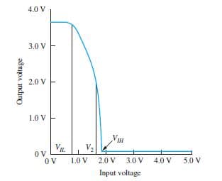
Transcribed Image Text:4.0 V
3.0 V
2.0 V
1.0 V
VIH
V2
VIL
OV
OV
1.0 V
2.0 V 3.0 V
4.0 V
5.0 V
Input voltage
Output valtage
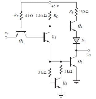
Transcribed Image Text:+5 V
Rs
130 2
RB
4 k2 1.6 k2
RC
D1
1kQ
1 k2
3 k2
Os
Expert Solution
This question has been solved!
Explore an expertly crafted, step-by-step solution for a thorough understanding of key concepts.

Step by step
Solved in 5 steps with 2 images

Knowledge Booster


Learn more about
Need a deep-dive on the concept behind this application? Look no further. Learn more about this topic, electrical-engineering and related others by exploring similar questions and additional content below.Recommended textbooks for you
EBK ELECTRICAL WIRING RESIDENTIAL
Electrical Engineering
ISBN:
9781337516549
Author:
Simmons
Publisher:
CENGAGE LEARNING - CONSIGNMENT
EBK ELECTRICAL WIRING RESIDENTIAL
Electrical Engineering
ISBN:
9781337516549
Author:
Simmons
Publisher:
CENGAGE LEARNING - CONSIGNMENT