5 5♫ 8 40°C R-22 QAA = 50 kW 40°C mB = 0.3 kg/s B -20°C Tin = 10°C 9 Ⓡ funny (mm) 3 1 The above refrigeration system uses R-22 as the refrigerant, determine: 1. Enthalpies at each point of the cycle in kJ/kg 2. Total mass of refrigerant that circulates the system in kg/s 3. Total refrigerating capacity in TOR 4. Total compressor power in kW 5. Heat rejected in the condenser kW 6. Heat rejected in the intercooler in kW 7. Coefficient of Performance 8. Draw the P-h Diagram
5 5♫ 8 40°C R-22 QAA = 50 kW 40°C mB = 0.3 kg/s B -20°C Tin = 10°C 9 Ⓡ funny (mm) 3 1 The above refrigeration system uses R-22 as the refrigerant, determine: 1. Enthalpies at each point of the cycle in kJ/kg 2. Total mass of refrigerant that circulates the system in kg/s 3. Total refrigerating capacity in TOR 4. Total compressor power in kW 5. Heat rejected in the condenser kW 6. Heat rejected in the intercooler in kW 7. Coefficient of Performance 8. Draw the P-h Diagram

Principles of Heat Transfer (Activate Learning with these NEW titles from Engineering!)
8th Edition
ISBN:9781305387102
Author:Kreith, Frank; Manglik, Raj M.
Publisher:Kreith, Frank; Manglik, Raj M.
Chapter8: Natural Convection
Section: Chapter Questions
Problem 8.46P

Related questions
Question
100%
No. 1~6 are answered. Proceed to no.7
4. Total compressor power in kW
From the p-h diagram, we can infer that the compressor power is given by:
Compressor power =
m ( h2 − h1 ) + m(h4 − h1) = m [ ( h2 − h1 ) + (h4 − h3) ] kWm ( h2 - h1 ) + m (h4 - h1) = m ( h2 - h1 ) + (h4 - h3) kW
Compressor Power= 0.622 [ ( 425.65 − 400.91 ) + (427.74 − 408.6) ] kWCompressor Power= 0.622 ( 425.65 - 400.91 ) + (427.74 - 408.6) kW
= 27.2934 kW
This is the required value of total compressor power in kW.
5. Heat rejected in the condenser in kW
Heat rejected in the condenser = m (h4 − h5 ) = 0.622 kg/s (427.74 − 249.71) kWHeat rejected in the condenser = m (h4 - h5 ) = 0.622 kg/s 427.74 - 249.71 kW
Heat rejected in the condenser = 110.7347 kW
6. Heat rejected in the intercooler in kW
Heat rejected in the intercooler = m ( h2 − h3 ) = 0.622 (425.65 − 408.6) kW Heat rejected in the intercooler = m ( h2 - h3 ) = 0.622 (425.65 - 408.6) kW
Heat rejected in the intercooler = 10.6051 kW
Transcribed Image Text:Solution:
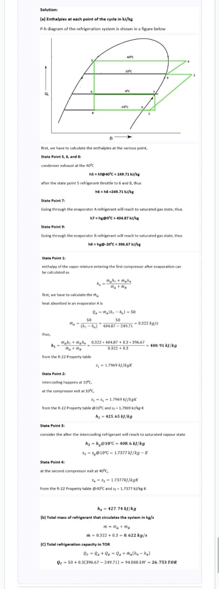
(a) Enthalpies at each point of the cycle in kJ/kg
P-h diagram of the refrigeration system is shown in a figure below
h
first, we have to calculate the enthalpies at the various point,
State Point 5, 6, and 8:
condenser exhaust at the 40°C
h5hf@40°C=249.71 kJ/kg
after the state point 5 refrigerant throttle to 6 and 8, thus
h6h8 249.71 kJ/kg
State Point 7:
Going through the evaporator A refrigerant will reach to saturated gas state, thus
h7 = hg@0°C = 404.87 kJ/kg
first, we have to calculate the th
heat absorbed in an evaporator A is
thus,
State Point 9:
Going through the evaporator B refrigerant will reach to saturated gas state, thus
h9hg@-20°C = 396.67 kJ/kg
h.
State Point 1:
enthalpy of the vapor mixture entering the first compressor after evaporation can
be calculated as
th-
m+
State Point 2:
40°C
10°C
h₁:
Tha+ma
from the R-22 Property table
0°C
-20°C
intercooling happens at 10°C,
at the compressor exit at 10°C,
mah+maha
m₂ + the
Qama(₂-₂)-50
50
50
(hy-h₂) 404.87-249.710.322 kg/s
0.322-404.87+0.3-396.67
0.322 +0.3
State Point 4:
at the second compressor exit at 40°C,
8₁1.7969 kJ/kgk
8₂81.7969 kJ/kgk
from the R-22 Property table @10°C and s2 = 1.7969 kl/kg-K
h₂425.65 kJ/kg
State Point 3:
consider the after the intercooling refrigerant will reach to saturated vapour state
hy-h@10°C-408.6 kJ/kg
$₂8@10°C 1.7377 kJ/kg-K
(C) Total refrigeration capacity in TOR
881.7377kJ/kgk
from the R-22 Property table @40°C and 5= 1.7377 kl/kg-K
400.91 kJ/kg
h₂-427.74 kJ/kg
(b) Total mass of refrigerant that circulates the system in kg/s
m-ma+ma
in-0.322 +0.3-0.622 kg/s
QTQ+Q₂Q₁ + m₂(h₂h₂)
Qr 50+ 0.3(396.67-249.71)-94.088 kW-26.753 TOR
Transcribed Image Text:5♫
8
40°C
R - 22
QAA
= 50 kW
0°C
mB = 0.3 kg/s
B -20°C
4
Tin = 10°C
www
ww
3
2
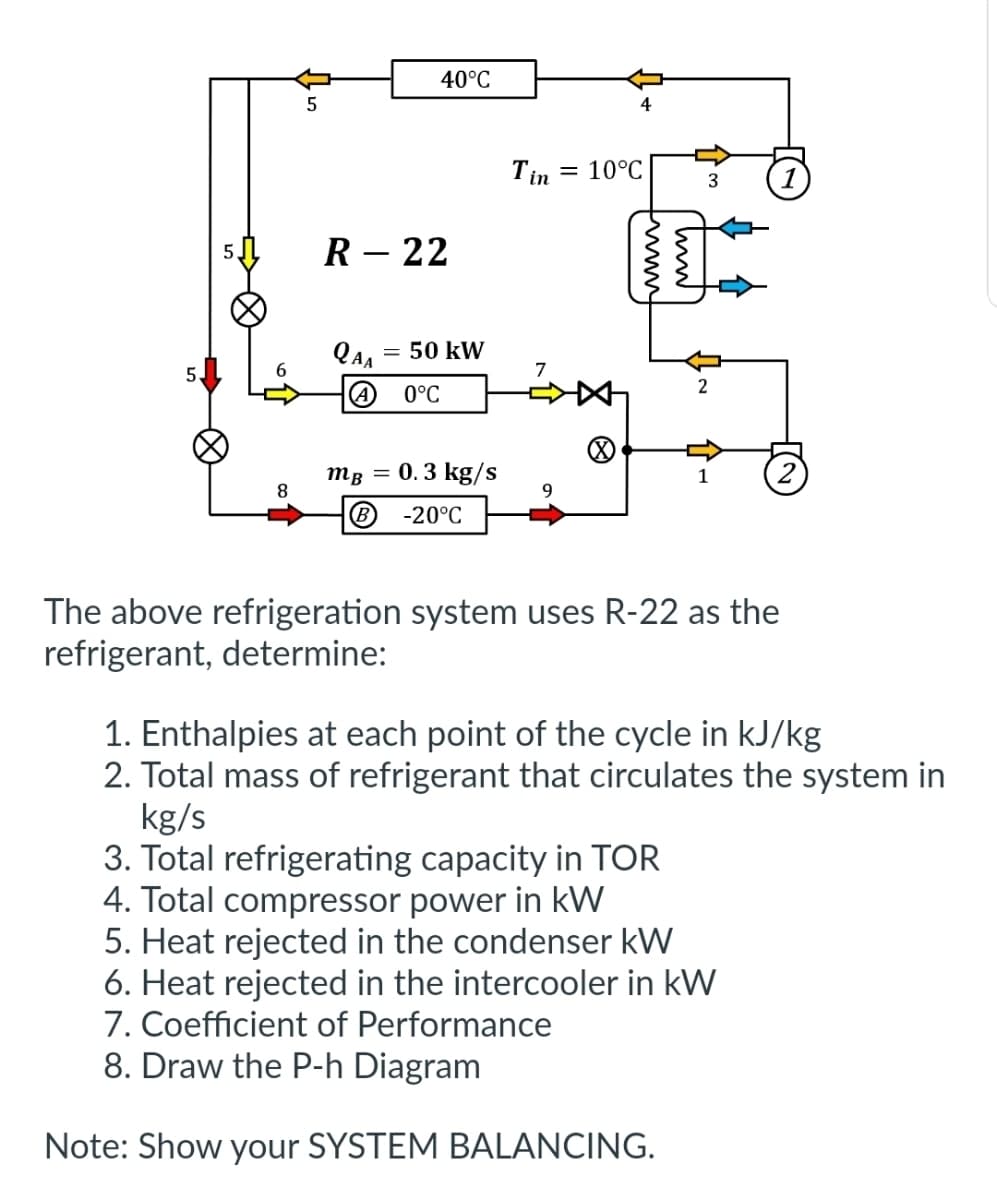
The above refrigeration system uses R-22 as the
refrigerant, determine:
1. Enthalpies at each point of the cycle in kJ/kg
2. Total mass of refrigerant that circulates the system in
kg/s
3. Total refrigerating capacity in TOR
4. Total compressor power in kW
5. Heat rejected in the condenser kW
6. Heat rejected in the intercooler in kW
7. Coefficient of Performance
8. Draw the P-h Diagram
Note: Show your SYSTEM BALANCING.
Expert Solution
This question has been solved!
Explore an expertly crafted, step-by-step solution for a thorough understanding of key concepts.

Step by step
Solved in 3 steps with 2 images

Knowledge Booster


Learn more about
Need a deep-dive on the concept behind this application? Look no further. Learn more about this topic, mechanical-engineering and related others by exploring similar questions and additional content below.Recommended textbooks for you
Principles of Heat Transfer (Activate Learning wi…
Mechanical Engineering
ISBN:
9781305387102
Author:
Kreith, Frank; Manglik, Raj M.
Publisher:
Cengage Learning

Refrigeration and Air Conditioning Technology (Mi…
Mechanical Engineering
ISBN:
9781305578296
Author:
John Tomczyk, Eugene Silberstein, Bill Whitman, Bill Johnson
Publisher:
Cengage Learning
Principles of Heat Transfer (Activate Learning wi…
Mechanical Engineering
ISBN:
9781305387102
Author:
Kreith, Frank; Manglik, Raj M.
Publisher:
Cengage Learning
Refrigeration and Air Conditioning Technology (Mi…
Mechanical Engineering
ISBN:
9781305578296
Author:
John Tomczyk, Eugene Silberstein, Bill Whitman, Bill Johnson
Publisher:
Cengage Learning