5 kN A В C 3 m 5 kN F D а 3т 3 m a 5 kN | H I G


Q: For the truss shown below is supported by a pin at A and roller at F. If it is loaded with P (kips)…
A:
Q: Q1- For the shown truss , the force in member (BH) is : a) - 47.1 KN (C) b) 50 KN (T) c) 60 KN (T)…
A:
Q: For the truss shown, determine the forces in members (a) BD; and (b) BF. -4 m-- 4 m--4 m- B -4 m- A…
A:
Q: Compute the force in member BD in kN. P1 - 117 kN, P2 - 49 kN and x- 7.1 m. Nrite numerical value…
A: P1=117kN P1=49kN To find force in member BD
Q: Determine all force the truss Shown mem bers of 600 4 m 4m
A: Above given truss
Q: Determine the force in DC member of the truss, and state if the members are in tension or…
A:
Q: AD supported by a rod (truss D shown below. Beam Take EI = 5 * 103 kN.m² for the beam, and AE = 1000…
A: The free body diagram of the body is shown below, The algebraic summation horizontal force should…
Q: Determine the force in member EB for the truss shown. - 2 m 1.5 m E -2 m F 2 m D B 11 kN 22 kN O…
A:
Q: 2-3. If the load P on the beam causes the end C to be displaced 10 mm downward, determine the normal…
A: The given figure is shown below:
Q: 100 kN 100 kN E |D 35 kN 3 m C 7 m В 4 m -3 m- -3 m- 4 m-
A:
Q: Determine the forces in members BC and CF of the loaded truss. Enter a positive number if in…
A:
Q: Determine the forces in members BC and CF of the loaded truss. Enter a positive number if in…
A: This question is related to the Truss from Structural Analysis. In this question we calculate force…
Q: Determine the forces in members BC and CF of the loaded truss. Enter a positive number if in…
A:
Q: Determine the forces in members EH and El of the double Fink truss (positive if in tension, negative…
A:
Q: From the given truss shown, it is supported by a hinge at A and roller at E. a. Determine the force…
A:
Q: classify, the truss, and find the ndicaded bar force, and the reactions, 20k A Bd-? so 5k tok 6 @…
A: Consider the following free body diagram: The above truss is a two dimensional truss. Check for…
Q: F6-11. Determine the force in members GF. GD, and CD of the truss. State if the members are in…
A:
Q: hat is the approximate axial force in girder EF of the frame shown? Use the port H 30 kN 6 m 10 kN D…
A: The portal method is based on the assumption that, for each storey of the frame, the interior…
Q: Determine the forces in members EH and El of the double Fink truss (positive if in tension, negative…
A:
Q: Compute the bar forces in the lettered bars of the truss shown. P P P P P Ja 45% 45° a
A:
Q: Determine the force in members DF and DE of the truss shown. 30 kN 20 kN D F 1.5 m 2 m |C E -2 m-2…
A:
Q: EI - 3*10" KN.m² Q/ For the beam shown in Pig. a1). Find all moments (Use s.D.M)
A: The beam is a horizontal member of the building or structure. It can use to transfer the load from…
Q: culate the force in each member of the truSs snown. State whetner each member iS in tension or…
A:
Q: Determine the vertical displacement of joint D. The truss is made from A992 steel rods having a…
A: Given : - The truss is made from A992 steel rods having a diameter of 30 mm is given Point load of…
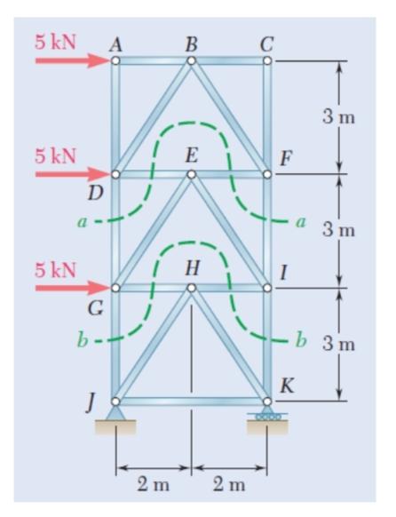
Q: 5 kN A B C 3m 5 kN I E F D a 3 m 5 kN | H I G -b 3m b-- K 2 m 2 m
A: Trusses are a basic structural component in architectural designs. These are mainly in buildings…
Q: Sn Determine the approximate force in member BC for the truss shown Select one O a 1000 N O b.ON Oc…
A: The FBD of the truss is shown below:
Q: Determine the forces in members BC and CF of the loaded truss. Enter a positive number if in…
A:
Q: Determine the forces in members BC and CF of the loaded truss. Enter a positive number if in…
A:
Q: B h 0.7 m 1 kN 0.4 m -0.6 m 1.2 m
A: ∈FY =0=> CY =WY+1∈MD =0CY×0.6=1×(1.2+0.6)CY =3KNWY =2KN∈FX =0DX =0a) when h =0.1mθ…
Q: A kN -2.5 m- D 1.5 kN . 4 m 3 kN F 4 m B 3 kN 4 m A H -4 m- Hy = AY= hine roller
A: given tower truss to find forces in members BG, FG, CF and EF using method of sections.
Q: 3) A truss is subjected to a load at B and C. 8 kN 1.5 8 kN 1.5 4 m 2.5 A) Compute the force in…
A: A) Compute the force in member BE. B) Compute the force in member AE. C) Compute the force in member…
Q: etermine the force in each member of the truss shown by method of joint. Use a = 1.2 m, b= 1.4 m,…
A: to find force in all members of the truss
Q: Determine the force in members DG and FI of the truss shown.(Hint: Use section aa.)
A: The given figure is shown below:
Q: 3m 3m H. D. 3m 9m | 9m 9m 3m A 9m- 10 kN 10 kN 1. For the truss shown, Determine the Bar Forces AB,…
A:
Q: Draw the S.F.D and B.M.D for the girder in the system shown in Fig. (5).. 230 2m 60 kN/m 4 m 2 m →
A: The girder system is given, we need to draw Shear force and bending moment diagram
Q: Determine the force in each member of the loaded truss. All triangles are 3-4-5. Enter a positive…
A:
Q: Determine the force in each member of the loaded truss. All triangles are 3-4-5. Enter a positive…
A: From the given question it is required to calculate the force in each member of the loaded truss.
Q: Determine the force in members CD, OF, and EF and indicate if the members * ?are in tension or…
A: To find force in CD EF DF
Q: The bar DA is rigid and is originally held in the horizontal position when the weight W is supported…
A: Given above diagram we have to find strain in DE
Q: Determine the force of the DE member (FDE) of the truss and state if the member is in tension or…
A: The given data is: P1 = 10 kN P2 = 20 kN
Q: Determine the forces in members BC and CF of the loaded truss. Enter a positive number if in…
A: Find force in member BC and CF. As length of member is not given but slope of each member is…
Q: The bar DA is rigid and is originally held in the horizontal position when the weight W is supported…
A: Given data Span length Displacement Cross sectional area Youngs modulus
Q: The truss shown is supported by a pin at A and a roller at F. Two force are applied to the truss.…
A:
Q: Problem #3 Am D B -2 m- 2 m- -2 m BkN C KN Y KN Determine the force in each member of the truss.…
A:
Q: Determine the resultant forces at pins B and C on member ABC of the four-member frame.
A: The resultant forces at pins B and C are nothing but reactions at members BE and CD. The reactions…
Q: Determine the force in members GJ and IK of the truss shown.(Hint: Use section bb.)
A: Consider the free-body diagram of the truss along the section b-b. Calculate the force in the…
Q: -4m 4m- F E Given: Loads as shown on the -10 m -10 m G truss. 10m Find: The force in members GB and…
A:
Q: Problem A truss is subjected to the following forces as shown. Determine: (a.) The magnitude of the…
A: AH is the horizontal reaction at joint A AV is the vertical Reaction at joint A BV is the vertical…
Q: 1.3-7 A plane truss has a pin support at A and a roller support at E (see figure). (a) Find…
A:


Step by step
Solved in 2 steps with 1 images


- A built-up section consisting of W 350 x 90 with two 12 – mm plates welded to form a box section as shown in figure. The section is used as a column 10 meters long. The column is fixed at both ends, and braced at mid height about the weak axis (Y-axis). Use Fy = 248 MPa. Properties of W350x90: bf=250mm tf=16.4mm d=350mm tw=9.5mm Ix=226x10^6 mm^4 Iy=44.54x10^6 mm^4 A=11,550 mm^2 a. Determine the effective slenderness ratio of the column with respect to lateral buckling about the x-axis. b. Determine the effective slenderness ratio of the column with respect to lateral buckling about the y-axis. c. Determine the axial load capacity of the column in kN.A flooring system consists of parallel I-beam sections spaced at 3 m on centers with simple spans of 6m. The beam supports a 200mm thick slab that laterally supports the top of the beams. The flooring system is designed for a superimposed load of 1750 N/m^2 The properties of the I-beam sections are: d= 352mm, tw= 7mm bf=170 mm, tf= 10mm Ix= 0.00012m^4, W= 44.85 kg/m Fy- 248 MPa,E= 200,000 GPa 1. Calculate the plastic section of the steel section in mm^3 2. Calculate the nominal strength (kN.m) of an individual beam if it is laterally supported by the concrete slab. 3. Calculate the unfactored service dead load on an individual beam in kN/m 4. Calculate the maximum service live load (kPa) the beam can sustain under LRFD provisions using φb= 0.9 5. Calculate the maximum live load (kPa) the beam can sustain under ASD provisions using Ωb=1.67At-beam has a width of flange equal to 700mm and a thickness of 100mm. It has an effective depth of 450mm and the width of the web section is 350mm. It is reinforced at the bottom with a steel area of 2925sq.mm. fc'=17.24MPa, fy=413.7MPa. The depth of the compression block is _mm. A. 136.00mmB. 146.00mmC. 126.00mmD. 156.00mm
- The simply supported beam consists of a W530 × 66 structural steel wide-flange shape [E = 200 GPa; I = 351 × 106 mm4]. Determine(a) the beam deflection at point A.(b) the beam deflection at point C.Assume P = 44 kN, w = 87 kN/m, LAB = 4.0 m, LBC = 4.0 m, LCD = 4.0 m, LDE = 2.0 m.Answer:vA = mmvC = mmM13A floor system is supported by WF A36 steel beams 7.7m long and spaced 3.8m on centers. The beams are simply supported at their ends and are laterally supported over the entire span. Assume compact section and neglect beam self-weight. The properties of the beam section are: d = 559 mm, tw = 47mm, bf = 299mm, tf = 57mm, k = 72mm, shape factor SF= 1.2, Sx= 8478x10^3. Use allowable deflection (1/360) of beam span. Calculate the ULTIMATE floor load in KPa that the beam can carry against SHEAR. Express your answer in 2 decimal places
- A steel column carries an axial load of 785 kN and a moment of 72 kN-m at the top and moment at the bottom which is only70% of the moment at the top. The two moments are in opposite direction and applied about the x-axis and the steel section has the following properties: A = 12818 mm2rx =109 mmry= 94 mmSx = 1200 x 103 mm3K= 1.0L= 3.6 mE = 200,000 MpaFy = 248 MpaUse NSCP specification for compressive stress and Fb =148 Mpa. Questions:From the Interaction Formula, compute the interaction value. Assume that the column is braced against joint translation (sidesway).Repeat Prob. 3-5 using singularity functions exclusively (including reactions).i want handwritten and correct I have attached final sol pls do it fullcolumn section = ISHB 450 Bracket plate thickness in mm =11 p=450KN E=330mm p=55mm bolt size =M20
- A steel column carries an axial load of 787 kN and a moment of 69 kN-m at the top and moment at the bottom which is only70% of the moment at the top. The two moments are in opposite direction and applied about the x-axis and the steel section has the following properties:A = 12974 mm2rx= 109 mmry= 94 mmSx = 1200 x 103 mm3K=1.0L= 3.6 mE = 200,000 MpaFy = 248 MpaUse NSCP specification for compressive stress and Fb =148 Mpa. Questions:Determine the Compressive Stress if Axial load only existed.A steel column carries an axial load of 787 kN and a moment of 69 kN-m at the top and moment at the bottom which is only70% of the moment at the top. The two moments are in opposite direction and applied about the x-axis and the steel section has the following properties:A = 12974 mm2rx= 109 mmry= 94 mmSx = 1200 x 103 mm3K=1.0L= 3.6 mE = 200,000 MpaFy = 248 MpaUse NSCP specification for compressive stress and Fb =148 Mpa. Questions:Determine the Compressive Stress if Axial load only existed. Note: The answer should close 60 MPAQuestion:- A 7.5 meters long simply supported structural steel beam carries two concentrated loads P at every third points. Use A 572 Grade 65 steel with Fy=448.18 MPa. The beam is W310x23.8 section having the given properties. A=3040mm² d= 305mm tw= 5.6mm bf=101mm tf= 6.7 mm Ix= 43x10⁶ mm⁴ Iy=1.2x10⁶mm⁴ a) Calculate the allowable bending stress of the compression flange of beam 7.5 fully supported against lateral movement. b) Based from the previous question, calculate the value of concentrated load P that the beam could support safety.