5. By applying Mesh analysin, find current in the 150 resistor of the network shown in Fig 15 10 200
5. By applying Mesh analysin, find current in the 150 resistor of the network shown in Fig 15 10 200

Power System Analysis and Design (MindTap Course List)
6th Edition
ISBN:9781305632134
Author:J. Duncan Glover, Thomas Overbye, Mulukutla S. Sarma
Publisher:J. Duncan Glover, Thomas Overbye, Mulukutla S. Sarma
Chapter6: Power Flows
Section: Chapter Questions
Problem 6.61P

Related questions
Question
By applying Mesh analysis, find current in the 15 Ω resistor of the network shown in
Fig.
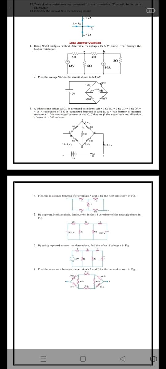
Transcribed Image Text:12. Three 4 uhm resistances are connected in star connection. Whunt will be its delta
equivalent
13.Calcutate Uie current b in the follewing einuit
68
4-2A
- 7A
4= 3A
Long Answer Question
1. Using Nodal analysis method, determine the voltages Va & Vb and current through the
6 ohm resistance,
20
12V
10A
2. Find the voltage VAB in the circuit shown in below?
100
300
T1ov
10V
200
3. A Whentstone bridge ABCD in arranged as follows: AB - 10; B - 2 0; CD - 3 0; DA -
4 0. A reaistance of 5 a in connected between B and D. A 4-volt battery of internal
resistance 10 is connected between A and C. Calculate i the magnitude and direction
af current in 50 resistor.
10
t1=1,+
10
4V
4. Find the resilatance between the terminals A and B for the network ahown in Fig
ww
www
5. By applying Menh analysin, find current in the 15 g resistor of the petwork shown in
Fig.
20
15
10
r400 V
S0 200 v T
6. By using repeated source transformations, find the value of voltage v in Fig.
40 V
E20
7. Find the resistance between the terminals A and B for the network ahown in Fig
100
ww
Sma
-300
Expert Solution
This question has been solved!
Explore an expertly crafted, step-by-step solution for a thorough understanding of key concepts.

Step by step
Solved in 3 steps with 2 images

Knowledge Booster


Learn more about
Need a deep-dive on the concept behind this application? Look no further. Learn more about this topic, electrical-engineering and related others by exploring similar questions and additional content below.Recommended textbooks for you
Power System Analysis and Design (MindTap Course …
Electrical Engineering
ISBN:
9781305632134
Author:
J. Duncan Glover, Thomas Overbye, Mulukutla S. Sarma
Publisher:
Cengage Learning
Power System Analysis and Design (MindTap Course …
Electrical Engineering
ISBN:
9781305632134
Author:
J. Duncan Glover, Thomas Overbye, Mulukutla S. Sarma
Publisher:
Cengage Learning